


Part 1 – Introduction
16
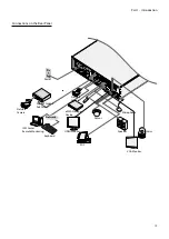
Rear Panel Connections
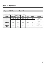
Power Cable Connection
Connect the power cable to this port. This NVR does not
feature a separate power on/off button and will turn on
the moment power is supplied.
•
Organize the power cable so that it will not cause
people to trip over or become damaged from chairs,
cabinets, desks, and other objects in the vicinity. Do
not run the power cable underneath a rug or carpet.
•
The power cable is grounded. Do not modify the
power plug even if your power outlet does not have
a ground contact.
•
Do not connect multiple devices to a single power
outlet.
Caution – Shock hazard
Disconnect all power sources
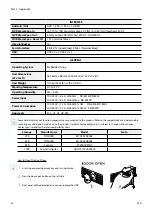
Video Connection
●
SFP Video In Port
These ports are used to connect to higher devices that
are some distances away via optical cables. You can
connect Gigabit Fiber Media Converters (Optional:
DA-MC1101) or external hubs (Optional: DH-2112PF,
DH-2128PF, DH-2212PF) to form a network. The NVR
recognizes DirectIP network cameras automatically.
•
These ports operate in Full Duplex mode only.
•
When the network is connected normally, the LED
lights up. Also when data transmission over the
network is in progress, the LED flashes.
•
For more information on SFP modules supported
by the SFP Video In Port, refer to Supported SFP
Transceiver Module List on page xx.
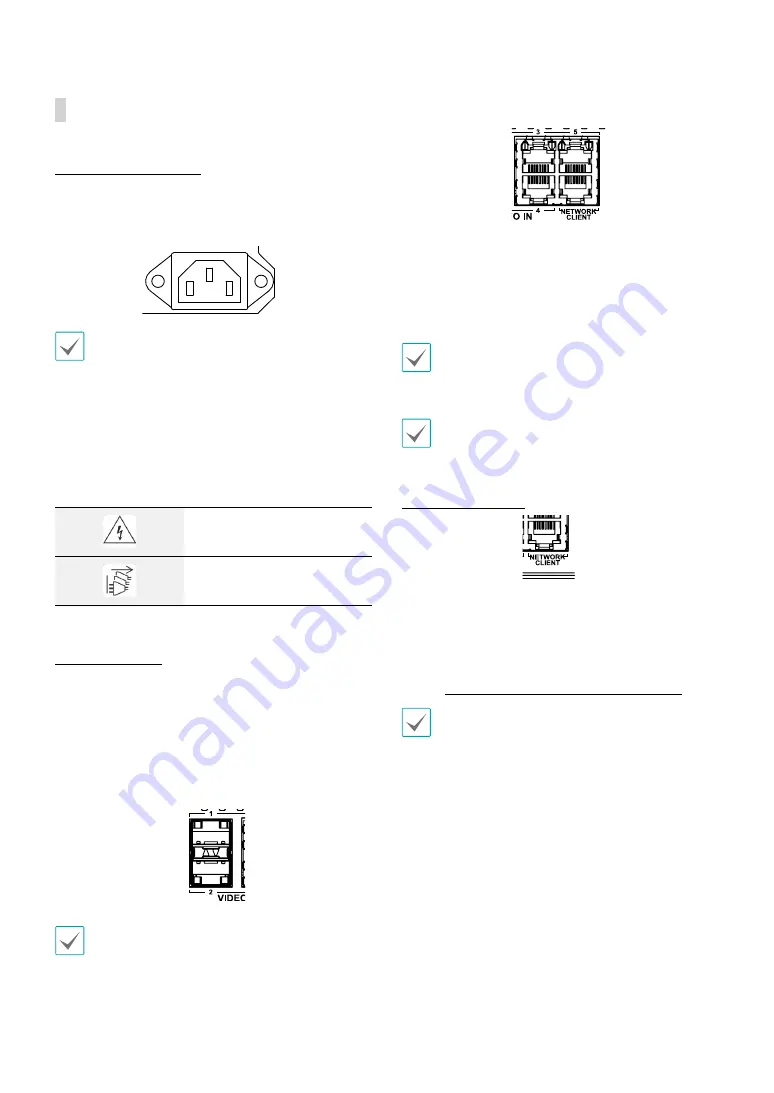
●
RJ45 Video In Port
Connect network cameras or video encoders to the NVR
using RJ-45 cable (Cat5, Cat5e, or Cat6). In addition to
cameras or video encoders, you can connect external
hubs (Optional: DH-2112PF, DH-2128PF, DH-2212PF) to
form a network. The NVR recognizes DirectIP network
cameras automatically.
Green LED on the right will turn on if connected to a
1000 BASE-T network. Orange LED on the left will then
flash once a link has been established.
•
For stable video transmission, it is recommended
to connect less than 32 network cameras or video
encoders to a single Video In port.
Network Connection
This NVR is capable of connecting to networks via an
ethernet connector. Connect an RJ-45 cable (Cat5,
Cat5e, or Cat6) to the NVR's network port. It's possible to
operate and upgrade the NVR remotely over a network.
Fore more information on ethernet connection setup,
refer to
Network Setup in the operation manual
.
•
Connector directions may vary depending on the
NVR model.
•
Green LED on the right will begin to flash if
connected a 1000 BASE-T network. Orange LED
on the left will then flash once a link has been
established.


