background image

Part 1 – Introduction

21

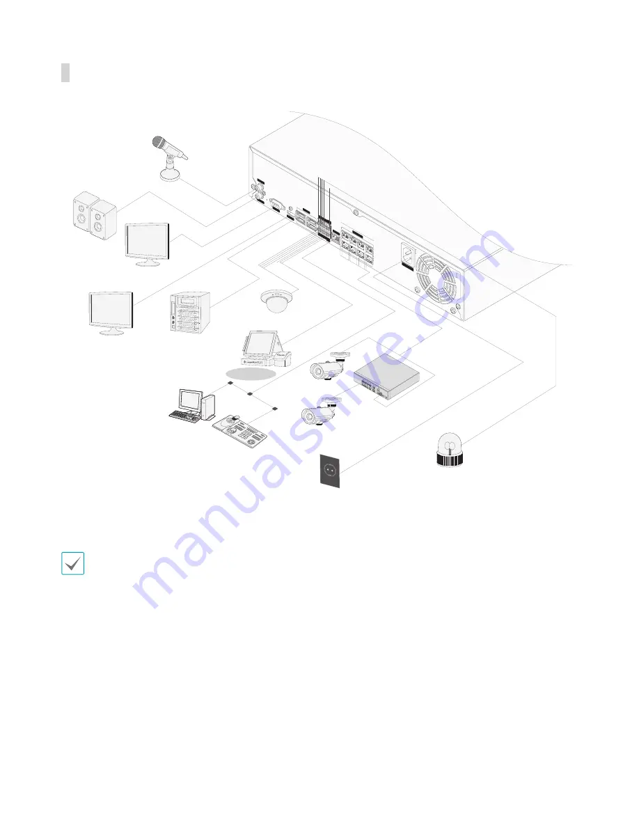
Connections on the Rear Panel

AUDIO OUT

NC     C

     NO   A

R I   G  RS -4

85

-          +

A/1   A/2

    A/3   A

/4      G  

Tx        R

x

RS    -23

2

AUDIO IN

VGA OUT

HD OUT

NET

WORK

VIDEO IN

eSA

TA

1

3

2

4

A

C

E

G

B

D

F

H

100-240V~

Direc

tIP™ S

witch

Microphone

Speaker

VGA Monitor

HDMI Monitor

eSATA Storage 
Device

Sensor

DirectIP™ Gigabit 
PoE Switch

Keyboard

Power

Alarm

POS

IDIS Center 
Remote 
Monitoring

Camera

Camera

Network

This connection diagram is for the DR-6100 Series.

Summary of Contents for DR-6100 Series

Page 1: ...Powered by Network Video Recorder Operation Manual DR 6100 Series DR 4100 Series...

Page 2: ...e instructions contained in this operation manual It is recommended that first time users of DirectIP Network Video Recorder and individuals who are not familiar with its use seek technical assistance...

Page 3: ...se User s Caution Statement Caution Any changes or modifications to the equipment not expressly approved by the party responsible for compliance could void your authority to operate the equipment Copy...

Page 4: ...in conjunction with protective equipment that minimizes damage from power outages and lightning strikes Presents fire electric shock and physical injury hazards Make sure to turn off the product befo...

Page 5: ...oduct Do not use water thinner or organic solvents Failure to do so can damage the product s finish and presents malfunction or electric shock hazard Power Voltage fluctuation of the power supply must...

Page 6: ...Caution Failure to comply can lead to minor injury and or product damage Installation Do not set up the product in an area that is exposed or susceptible to strong magnetism radio waves and or impact...

Page 7: ...ing Rec LED on the front of the product indicates data is being recorded on the HDD Regularly check to see if the Rec LED is flashing Changing the settings in order to continue recording data once the...

Page 8: ...25 Setup Wizard 25 Camera Registration 26 Camera Scan Button 26 Camera View Buttons 27 Camera List Area 28 Video Display Area 28 Apply Cancel Buttons 29 Camera Registration Mode 29 Login 30 Live Mode...

Page 9: ...38 System Setup 38 General 38 Date Time 39 User 40 Storage 42 Monitoring 42 Camera Setup 44 General 44 Advanced Setup 44 Stream 47 Audio 47 Upgrade 48 Record Setup 48 General 48 Schedule 49 Pre Event...

Page 10: ...Storage 63 Part 4 Search 64 Time Lapse Search 64 Search Menu 65 Context Menu 68 Motion Search 68 Text In Search 69 Clip Copy 69 Print 70 Event Log Search 71 Overlapped Recording Search 72 Part 5 IDIS...

Page 11: ...aphic User Interface GUI and multilingual Multiple recording modes Schedule Event Pre Event and Panic Two USB 2 0 ports for connecting peripherals upgrading software and saving recording data 6 intern...

Page 12: ...inside to ensure that all the following accessories are included 1 2 3 4 5 6 7 8 9 0 DR 6100 4100 Series Power Cable Quick Guide Operation Manual and IDIS Center Program CD Optical USB Mouse IR Remot...

Page 13: ...unction Remote control sensor is located on the far left side of the front panel Ensure that the sensor remains unobstructed at all times If obstructed the sensor might not be able to receive remote c...

Page 14: ...arch menu on the top of the screen Press the button once more to close the menu Pressing and holding the Menu 1 2 3 4 5 6 7 8 9 button for 3 seconds while in Playback mode activates One Touch mode and...

Page 15: ...pherals such as a USB mouse or a USB printer to the NVR You can also use a USB to serial converter and connect multiple text in devices to the NVR at the same time It is also possible to connect a Pos...

Page 16: ...Part 1 Introduction 16 Connections on the Front Panel 1 2 3 4 5 6 7 8 9 0 1 2 3 4 5 6 7 8 9 0 Flash Memory Mouse USB HDD USB ODD IR Remote Control...

Page 17: ...0 240V 1 2 3 4 5 6 8 7 9 0 DR 4100 Series AUDIO IN AUDIO OUT VGA OUT eSATA NETWORK VIDEO IN NC C NO ARI G RS 485 A 1A 2A 3A 4 G Tx Rx RS 232 CAUTION TOREDUCETHERISKOFELECTRICSHOCK DONOTREMOVECOVER ORB...

Page 18: ...5 A 1A 2A 3A 4 G Tx Rx RS 232 3 4 A C E G B D F H 100 240V Connect network cameras to the NVR using RJ 45 cable Cat5 Cat5e or Cat6 In addition to cameras you can connect external hubs Optional DH 2112...

Page 19: ...E EFERSERVICINGTOQUALIFIED SERVICEPERSONNEL 1 3 2 4 A C E G B D F H 100 240V Press down on the button and insert the cable into the opening Release the button and then pull on the cable slightly to en...

Page 20: ...C NO ARI G RS 485 A 1A 2A 3A 4 G Tx Rx RS 232 CAUTION TOREDUCETHERISKOFELECTRICSHOCK DONOTREMOVECOVER ORBACK NOUSER SERVICEABLEPARTSINSIDE REFERSERVICINGTOQUALIFIED SERVICEPERSONNEL 1 3 2 4 CAUTION RI...

Page 21: ...IN VG A OU T HD OU T NE TW OR K VIDE O IN eS ATA 1 3 2 4 A C E G B D F H 10 0 24 0V DirectIP Switch Microphone Speaker VGA Monitor HDMI Monitor eSATA Storage Device Sensor DirectIP Gigabit PoE Switch...

Page 22: ...UT Button 6 PTZ Control Buttons 7 REGISTER MODE Button 8 THUMBNAIL Button 9 CALENDAR Button 0 KEYLOCK Button SETUP Button FREEZE Button LOG Button Enter Button Arrow Buttons ALARM Button SEQUENCE Butt...

Page 23: ...7 REGISTER MODE Button Used in Live mode to access Camera Registration mode 8 THUMBNAIL Button Used in Playback mode to access Thumbnail Search mode Thumbnail Search mode displays thumbnails of video...

Page 24: ...select menus and options c Playback Buttons Scans backward through the video at a fast rate Press to cycle through x2 x3 and x4 the speed Plays the video in normal speed and displays r on the screen...

Page 25: ...by navigating to the System menu and selecting Wizard 3 Specify whether the system has network access and then select Next 4 Select Network Configuration and then select Next Select either Auto Confi...

Page 26: ...tings 6 Enter in the Device Name field the NVR name you wish to register on the FEN server This is a unique NVR name that will be registered on the FEN server Once registered the name can be used to s...

Page 27: ...contact your retailer 3 From the Mode drop down list select Auto Scan LAN or IP Address Scan 4 Select Scan to commence scanning Only cameras that are connected to the NVR via video in ports can be sc...

Page 28: ...ates the camera s name Changing a camera s name in the video display area updates the camera list as well Following options can be accessed by right clicking on a camera list entry Add Camera Adds the...

Page 29: ...Camera Removes the registered camera Authentication Enter the necessary camera login info Color Control Adjusts the camera s color settings Information Displays the camera s basic information Title Ed...

Page 30: ...d for the admin account Select admin and then OK without entering a password to log in Leaving the admin account unassigned with a password poses a security risk Please assign a password at your earli...

Page 31: ...e account ID is shown If in the logged out state the login icon is shown 2 Layout Used to change the screen layout to single screen 2x2 3x3 4x4 5x5 or 6x6 3 Previous Next Group Loads the previous next...

Page 32: ...h for and play back saved data directly from the record table Event Log Search Select Search Mode Event Log Search to search for event logs and play back associated event recordings Setup Used to acce...

Page 33: ...and vice versa You can also change the direction by dragging on the mouse Also it s possible to use the mouse wheel to zoom in out Logging in with an account that has PTZ Control Authority is necessa...

Page 34: ...osition the PTZ Tools window Select the icon to hide the PTZ Tools window Event Monitoring When an event occurs the NVR automatically displays the channel linked to the event and shows the icon on the...

Page 35: ...is then loaded on to the selected page Repeat to assign other channels to the page 3 Press the Enter button to exit Edit Group Alternatively press the Menu button and then select Exit Group Edit to ex...

Page 36: ...e only Covert protection on cameras also applies to video recording playback All Channel Playback 1 Press the Menu button while in Live mode 2 Select the Search Mode icon and then select Time Lapse Se...

Page 37: ...option and then press the Enter button or left click on the option using the mouse 3 Change the setting and then select Apply or OK to save the change To apply default settings select the Default but...

Page 38: ...to select an upgrade package and upgrade the system Once the upgrade is complete the NVR will reboot automatically If an upgrade attempt fails an upgrade failure message will be displayed Refer to Err...

Page 39: ...ed to designate the system s time zone Refer to the map displayed on the screen and change the time zone using the mouse or the arrow buttons Use Daylight Saving Time Enables DST correction Time Sync...

Page 40: ...Specify the group s permission settings For more information on permission settings refer to the Group Permissions on page 41 3 Select User and then enter a user name 4 Select a group for the user and...

Page 41: ...e duration of inactivity specified under Auto Logout Group Permissions System Shutdown May shutdown the system from the system menu Upgrade May upgrade the system from the system menu System Setup Col...

Page 42: ...or recording purposes Disks that were used in different systems will show up as Other Select Information to check the saved data s time information or select Delete to erase the data Select Format to...

Page 43: ...hile alarm in is active Disk Almost Full Generates an event if the disk reaches the specified capacity 80 to 99 Disk Full Generates an event when all disks reach their maximum capacity Disk Bad Genera...

Page 44: ...ation about the camera as if it has been deactivated completely Advanced Setup Configure security and other advanced camera settings Video Adjust the camera image sensor settings such as white balance...

Page 45: ...options screen without saving the changes Image Sensor Options Mirror Select Horizontal or Vertical to flip the image horizontally and or vertically Video Style Select TV Color or PC Color Backlight C...

Page 46: ...e automatically Incandescent Fluorescent Cold Select a lighting type to apply the appropriate white balance Manual Adjust the white balance manually Adjust Red and Blue gain values Greater the value g...

Page 47: ...file settings Record Video Profile Set up 4 recording quality profiles Video Profile Select Live 1 Live 2 Remote or Custom available from Record Video Profile only Live 1 and Live 2 allows the user to...

Page 48: ...on using the Setup menus General Configure general recording settings Recycle When the recording disks become full the system overwrites existing data with new data starting with the oldest first If R...

Page 49: ...he network goes down this feature will transfer temporary data stored in the camera s buffer to the NVR when the network goes online again Use Panic Recording Enable disable Panic Recording Panic Reco...

Page 50: ...ecording commences as per the video profile selected for time under Setup When an event occurs the icon changes into icon and recording commences as per the video profile selected for events under Set...

Page 51: ...nt mode schedule exists in the schedule a warning message prompting you to add an event mode schedule will be displayed The warning message will appear even in Time Event mode Event Setup Refer to the...

Page 52: ...the specified number of blocks in order to trigger a Motion Detection event You may select a value between 1 and the number of blocks selected under Zone for daytime and nighttime each Actions Specify...

Page 53: ...hin the selection window Select All Select all blocks Clear All Clear all block selections Reverse All Clear all selected blocks within the screen and select all unselected blocks within the screen Tr...

Page 54: ...ent triggered alarm out channels and beeps Notify Configure to be notified of events by Mail LAN1 through 5 SNS Push and or Alert Window In order to use the Callback feature the NVR must be registered...

Page 55: ...not last for the specified duration of time will not be considered as events Actions Specify which actions to take when audio detection events occur Record Specify which cameras to begin linked recor...

Page 56: ...Feed new line is J Ignore String Specify a string to ignore from transaction records Case Sensitive Ignores case in strings designated under Transaction Start Transaction End Line Delimiter and Ignor...

Page 57: ...using the Setup menus General Network Bandwidth Limit Specify the network bandwidth limit Limiting the network bandwidth can affect the quality of Live video display on the remote program Remote Audi...

Page 58: ...r it to connect to the NVR To use the UPnP Universal Plug and Play feature select Use UPnP If using an IP router or NAT UPnP service allows the device to automatically forward the port to the NVR This...

Page 59: ...f the IP router or NAT Select Save after making changes to register the NVR s name to the FEN server If FEN has been configured correctly the FEN server s help desk information will be displayed in th...

Page 60: ...rver port number is 25 Select Test to send out a test mail using the current settings Select Use SSL TLS to use an SMTP server that requires SSL connections If you have configured the DNS Server setti...

Page 61: ...receive the event occured in NVR on the mobile phone Android iOS The NVR must be registered and set in mobile phone Display Setup Refer to the Menu Use on page 37 for basic information on using the Se...

Page 62: ...nts When an event occurs the corresponding channel flashes for 5 seconds Event Types Alarm In Audio Detection Check Alarm In Trip Zone Motion Tampering Video Loss Text In Panic Record Displays event s...

Page 63: ...s bad sector ratio is higher than as designated by the user Generates a system event Temperature N A Unable to detect the disk s temperature Good Operating within normal temperature range Bad Disk te...

Page 64: ...front panel or the remote control to select the menus and options Search menu can also be displayed by placing the mouse cursor on the upper portion of the screen CAM1 1 2 3 4 The Control Area consist...

Page 65: ...its original ratio 4 Alarm Pressing this button while the alarm has been activated resets all NVR alarm outputs including the built in buzzer 5 Database Record Search recording data contained in the...

Page 66: ...ough video recordings Playback controls have the same functions as their remote control counterparts Jog Shuttle Adjust the playback method and speed Jog shuttle s vertical indicator indicates the cur...

Page 67: ...rent playback position Use the arrow buttons on the front panel to move the current playback position in units of individual sectors Alternatively use the mouse to jump to the desired playback positio...

Page 68: ...dividual frames against their preceding frames This means slow and gradual movements no matter how long they persist will not be recognized In contrast Museum Search looks for changes in the specified...

Page 69: ...he options have been configured select Search to begin the search and return to the Text In Search setup window Clip Copy Clip Copy Select Export Clip Copy from the Search menu or press the remote con...

Page 70: ...peration manual For USB flash memory devices the NVR supports the FAT32 file format only Do not disconnect the USB cable or power off the USB device while USB Clip Copy is in progress Doing so can cau...

Page 71: ...elected From and To points will be searched If Check Time Overlap has not been selected events from the entire From and To range will be searched Use event filters to include exclude specific system e...

Page 72: ...00 6 00 Segment 1 Segment 2 When searching overlapped video recordings you can choose a specific point in time or a time frame If you use the Go to the Date Time option and select a point within the...

Page 73: ...window select LIVE PORT or PLAY PORT as the desired mode Enter the ID and password and click LOGIN to sign in using the selected mode If connecting by entering http web idisglobal com enter the NVR s...

Page 74: ...rompt Right Click and then select Run as administrator Type in netsh int tcp set global autotuninglevel disable and then press Enter Restart the computer to apply the change To enable auto tuning agai...

Page 75: ...locale is shown on the screen Enable Audio Enables audio transmission with remote locales Select to display buttons Enables transmission of audio to the remote locale via microphone Enables playback o...

Page 76: ...heck IDIS Web s version 3 Displays time information of the video recording from the remote DVR 4 Select the desired mode 5 Click to print the current video screen using a printer connected to the comp...

Page 77: ...able at the bottom displays recording data information for the selected date Select a point in time to display video from that moment If multiple recordings are available for the selected point in tim...

Page 78: ...n on the screen Enable Audio If audio was recorded with the video enabling this option plays audio upon playback limited to single screen playback Aspect Ratio Changes the aspect ratio of the video di...

Page 79: ...Disk Bad Clip Copy End Login Clip Copy Cancel Logout Clip Copy Failure Setup Begin Clip Copy User Setup End Clip Copy Begin Remote Setup Change Clip Copy Finished Remote Setup Failure Clip Copy Durati...

Page 80: ...104 Reboot Failure 404 USB Storage Device in Use 105 Improper File 405 Unsupported File System 106 Optical Drive Firmware Update Failure 500 Clip Copy in Progress Upgrade Not Available Clip Copy Error...

Page 81: ...t 26 Port in Use 7 Network Device Terminated 27 SSL Connection Failure 8 Unable to Connect No Available Port 28 Network Timeout 9 Server Not in Operation Unable to Connect 29 Network Device Host Timeo...

Page 82: ...on refer to the General on page 48 icon is shown but video is not being recorded If the Pre Event option has been enabled events will not be generated and and icons are shown The and icons appear when...

Page 83: ...Series Max 65 with 4HDDs DR 4100 Series Certifications FCC UL CE CB KCC KC Video Video In 8 16 32 Network Camera Video In Port 8 Monitor Out HDMI 1 HDMI VGA 1 DB15 Video Resolution 1920x1080 1680x105...

Page 84: ...bays DR 6100 Series 4 SATA2 bays DR 4100 Series External Storage 4 eSATA ports DR 6100 Series 2 eSATA ports DR 4100 Series Clip Copy Device USB Storage Device USB DVD RW USB Memory etc Some hard disk...

Page 85: ...4 F FEN 59 I IDIS Web 73 IP Address 58 L Live Mode 31 Login 30 M Motion Search 68 Mouse 38 O OSD 61 P Panic Recording 35 Pre Event 51 Print 70 PTZ Control 33 R Recording 35 Record Setup 48 S Schedule...

Page 86: ...IDIS Co Ltd For more information please visit at www idisglobal com Ver 1 00...

Reviews: