


Part 1 – Introduction
12
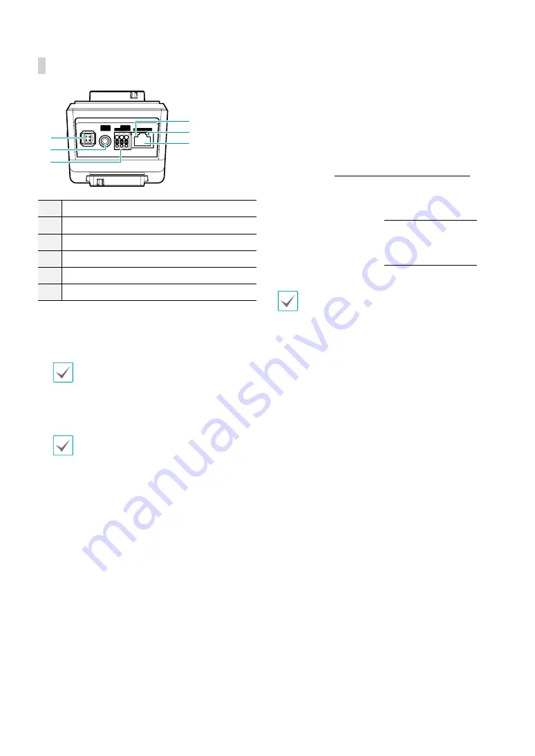
Back
1
2
3
4
5
6
VIDEO
OUT
DC 12V
FGND
NETWORK
+
-
1
Auto Iris Lens Connector
2
Video Out
3
Power
4
Network Port
5
Network LED
6
Power LED
•
Auto Iris Lens Connector
If using a DC type or P type auto iris lens, connect the
auto iris jack.
The lens must have a long auto iris jack.
•
Video Out
Connect he monitor.
Use these ports for previewing video and not
monitoring video.
•
Power
-
DC12V -/+
: Connect the two wires of the power
adapter to these ports. Be careful not to cross
the + and - wires. Booting will commence once
connected to a power supply.
-
FGND (Frame Ground)
: Used to ground the
device.
•
Network Port
Connect a Cat5e cable with an RJ-45 connector to
this port. If using a PoE switch, you can supply power
to the camera using an ethernet cable. For more
information on PoE switch use, refer to the switch
manufacturer's operation manual. You can configure,
manage, and upgrade this camera and monitor its
images from a remote computer over the network.
For more information on network connection setup,
refer to the
IDIS Discovery operation manual
.
•
Network LED
Indicates the network connection status. For more
information, refer to the
•
Power LED
Indicates the system's operating status. For more
information, refer to the
Press down on the button and insert the video out/
power connector cable into the opening. Release the
button and then pull on the cable slightly to ensure it
is held securely in place. To disconnect, press down on
the button again and pull the wire out.