


23
3-MEASURE
Tconst =s
is a time constant for the instrument response
rate. It is represented in seconds. This field setting affects
the integrating filter which increases or decreases the
instrument response rate to changes in flow rate. A higher
value corresponds to a more stable but slower
measurement. The most common values are from
1
to
5
seconds.
The acceptable range is
0
to
6,000.0
seconds. The
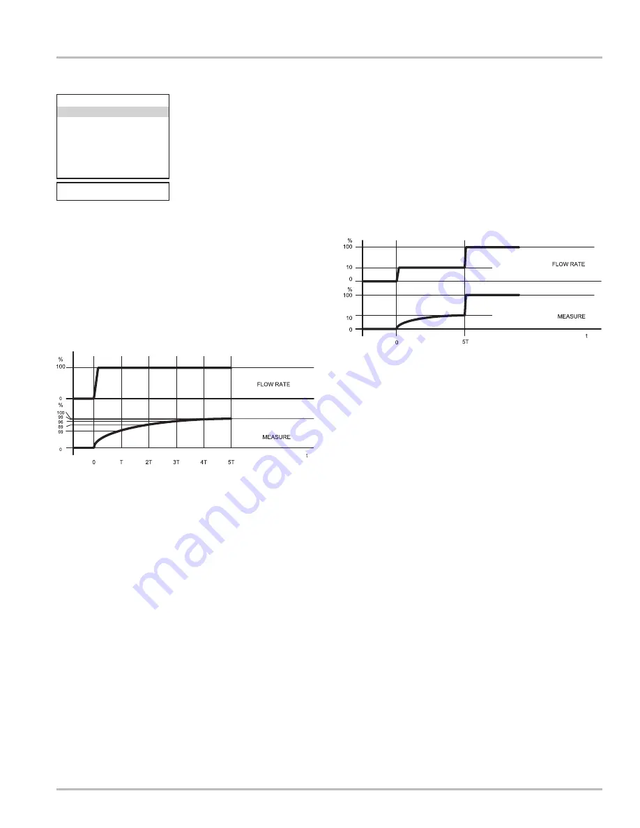
diagram below shows the response of the instrument for
a flow rate variation from 0 to 100% within the
T
time
constant period.
For applications such as dosing or short runs, this value
should be set to “
0
”. For applications where regulation
of valves or pumps is controlled by the converter, this
value is typically set in the lower range (
0.5
to
5
). A higher
value results in a more stable display of flowrate due to a
slower response to fluctuations.
Filter=s
represents the amount of filtering of noise of the
power supply frequency of 60 Hz. There are four options
for this field:
0.1
,
0.2
,
0.5
, or
OFF
. The higher the value,
the more filtering of the signal.
Skip thr=%
represents the acceleration threshold. This
is the limit beyond which a flow rate variation determines
an immediate response at the output, without being
filtered by the
Tconst=s
. The system allows the
instrument to have an immediate response for big
variations in the flow rate while filtering the response to
small variations.
The result is a more stable measurement. The value is
set as a percentage of the full scale value and may be
set from
0
to
125%
. If the value is set to
0%
, any flow
rate variation greater than
0.5%
of the full scale value
will immediately affect the outputs.
The diagram below shows the instrument response in
two cases: a flow rate variation from 0 to 10% completely
absorbed by the time constant effect, and a variation from
10 to 100% exceeding the acceleration threshold and
immediately sent to the output. There is always a
minimum time between flow measurement and outputs.
For applications such as dosing or short runs, this value
should be set to “
0
”. For applications where regulation
of valves or pumps is controlled by the converter, this
value is typically set in the lower range (~
20%
). A higher
value results in a more stable display of flowrate due to a
slower response to fluctuations.
Peak thr=%
is the peak cutoff threshold. This parameter
is used to set the maximum value of deviation of the actual
measure sample by comparison with an average one. If
the new value is higher than the set limit, then the value
is “cut” to the limit value. This function is used to make
the meter less sensitive to big disturbances of the flow
rate measurement. This can happen if there are solids
in suspension in the liquid and they hit against the
electrodes and cause spikes in the signal.
The permitted values of this function go from
0
to
125%
and are referred to the full scale value. If this parameter
is set to
0
, the peak detection function is disabled and
any new measure sample will be accepted and processed
as it is by the converter.
For applications such as dosing or short runs, this value
should be set to “
0
”. For applications where regulation
of valves or pumps is controlled by the converter, this
value is typically set in the upper range (
115%
to
125%
).
An example of this setting appears on the following page.
Programming Functions
Effect of Time Constant acceleration threshold
Effect of the Time Constant
0001.0
0.1
050
125
01.5
OFF
OFF
3-MEASURE
Tconst=s
Filter=s
Skip thr=%
Peak thr=%
Cut-off=%
Autocal.=
Autorange=
OFF
E.saving=
Summary of Contents for LIQUID CONTROLS HML210
Page 43: ...43 Notes...


