4
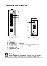
2 Structure and Interface
Figure 1 Front Panel
Figure 2 Top Panel
(1) Power 1 LED
(2) Power 2 LED
(3) 10/100Base-T(X) Ethernet port
(4) 10/100Base-T(X) Ethernet port connection status LED (green)
(5) 10/100Base-T(X) Ethernet port speed LED (yellow)
(6) Grounding screw
(7) Power terminal block
(8) DIP switches
Caution
:
It is recommended to purchase the connector cover for RJ45 port
(op ional) to keep ports clean and ensure switch performance.
SX5E-HU055B
PWR1
PWR2
5
3
2
1
4
(1)
(2)
(4)
(3)
(5)
PWR2
PWR1
/L
/L
- N
- N
OFF
ON
Ⅰ
Ⅱ
(6)
(7)
(8)
!


