


65
HS5E-K Interlock Switches with Key
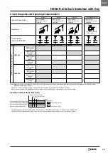
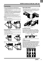
Circuit Diagrams and Operating Characteristics
Interlock Switch Status
Status 1
Status 2
Status 3
Rear Manual Unlock
• Door closed
• Machine ready to
operate
• Door closed
• Machine cannot be
operated
• Door opened
• Machine cannot be
operated
• Door closed
• Machine cannot be
operated
Door Status
Press rear unlocking
button. (Note)
Press
Circuit Diagram
(Example: HS5E-KVA)
11
23
42
54
12
24
41
53
LOCK
UNLOCK
53
41
24
12
54
42
23
11
LOCK
UNLOCK
11
23
42
54
12
24
41
53
LOCK
UNLOCK
11
23
42
54
12
24
41
53
LOCK
UNLOCK
Door
Closed (locked)
Closed (unlocked)
Opened
Closed (unlocked)
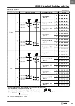
Model and Contact Configuration
HS5E-KVA
Monitor Circuit
(door closed)
11-12
Monitor Circuit
(door open)
23-24
Monitor Circuit
(locked)
41-42
Monitor Circuit
(unlocked)
53-54
HS5E-KVD
Monitor Circuit
(door closed)
11-12
Monitor Circuit
(door closed)
21-22
Monitor Circuit
(locked)
41-42
Monitor Circuit
(locked)
51-52
Note: When the operator is confined in a hazardous area, the actuator can be unlocked manually by pressing the rear unlocking button, which should be
accessed easily by the operator .
• The above contact configuration shows the status when the actuator is inserted and the switch is locked .
• Monitor circuit: Sends monitoring signals of protective door open/closed status or protective door lock/unlock status .
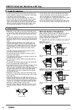
Operation Characteristics (Reference)
• The operating characteristics shown in the chart above are of the HS9Z-A51 actuator . For other actuators, add 1 .3 mm .
• The operation characteristics show the contact status when the actuator enters the entry slot of an interlock switch .
Approx.
26.4
Approx.
5.3
Approx.
6.9
Approx.
3.3 (Locked Position)
0
(Travel in mm)
(Actuator Insertion Position)
: Contacts OFF (Open)
: Contacts ON (Closed)
Monitor Circuit (door open, NO)
Monitor Circuit (door closed, NC)
Monitor Circuit (unlocked, NO)
Monitor Circuit (locked, NC)
HS5E-K


