


ICOM
Water treatment and conditioning of commercial
heating systems guide.
Where reference is made throughout these instructions I.S.813:2002
“Domestic Gas Installations” reference should also be made to
I.S.820:2000 “Non-Domestic Gas Installations” as applicable.
1.4 SAFE HANDLING
This boiler will require 2 or more operatives to move it to its
installation site, remove it from its packaging base and during
movement into its installation location. Manoeuvring the boiler
may include the use of a sack truck and involve lifting, pushing
and pulling.
Caution should be exercised during these operations.
Operatives should be knowledgeable in handling techniques when
performing these tasks and the following precautions should be
considered:
• Grip the boiler at the base.
• Be physically capable.
• Use personal protective equipment as appropriate, e.g.
gloves, safety footwear.
During all manoeuvres and handling actions, every attempt
should be made to ensure the following unless unavoidable and/
or the weight is light.
• Keep back straight.
• Avoid twisting at the waist.
• Avoid upper body/top heavy bending.
• Always grip with the palm of the hand.
• Use designated hand holds.
• Keep load as close to the body as possible.
• Always use assistance if required.
1.5 SAFE HANDLING OF SUBSTANCES
No asbestos, mercury or CFCs are included in any part of the
boiler or its manufacture.
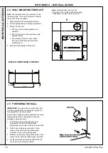
1.6 LOCATION OF BOILER
The boiler must be installed on a flat and vertical wall capable of
adequately supporting the weight of the boiler and any ancillary
equipment or on a boiler frame supplied in kit form.
The wall must be 90º (±5º) from the perpendicular. This is to allow
safe operation of the integral flue non return valve.
The boiler must not be fitted outside.
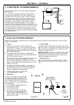
1.7 GAS SUPPLY
The local gas supplier should be consulted, at the installation
planning stage, in order to establish the availability of an adequate
supply of gas. An existing service pipe must NOT be used without
prior consultation with the local gas supplier.
A gas meter can only be connected by the local gas supplier or
by a suitably qualified Gas Safe registered engineer or in IE by a
competent person.
An existing meter should be checked, preferably by the gas
supplier, to ensure that the meter is adequate to deal with the
rate of gas supply required. A minimum working gas pressure of
17.5mbar MUST be available at the boiler inlet for Natural gas
and 32mbar for Propane.
Do not use pipes of smaller size than the boiler inlet gas connection.
The complete installation MUST be tested for gas soundness and
purged in accordance with the appropriate standards listed on page 8.
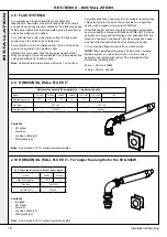
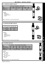
1.8 FLUE INSTALLATION
DANGER; ONLY USE IDEAL ROOM SEALED FLUE
GAS SYSTEMS. THE BOILER CE MARK IS VALID
ONLY IF THE APPLIANCE IS OPERATED WITH IDEAL
ROOM SEALED FLUE KITS. OTHER FLUE SYSTEMS
ARE NOT TESTED WITH THIS APPLIANCE.
DANGER; ONLY USE OPEN FLUE GAS SYSTEMS
WHERE THE BOILER AIR INLET KIT IS USED. THE
BOILER CE MARK IS VALID ONLY IF THE APPLIANCE
IS OPERATED WITH THE IDEAL AIR INLET KIT.
The flue kits are suitable for use with this boiler range only.
These kits and the associated options are suitable for both roof
and wall mounting applications.
The roof flue kits are suitable for both flat and pitched roof
termination, using either concentric or flue only terminals.
All flue options are connected using the flue adaptor fitted to the
boiler at the time of manufacture.
Additional information covering the selection and installation can
be found with this booklet.
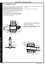
Weather Proofing
Where the flue passes through the roof line an adequate seal
must be made. This can be achieved by using either:
•
Flat weather collar
•
Pitched weather collar
Flue duct extension kits are available for concentric flue
configuration. These packs contain additional 1 metre ducts and
may be cut to the desired length.
Flue duct extension kits are available for open flue configurations.
These packs contain 2 x 1 metre ducts and may be cut to the
desired length.
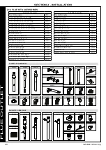
If obstructions prevent direct flue routing then both 90
o
and 45
o
elbows can be provided to offset the flue system.
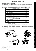
Terminal Position
Due to the high efficiency of the boilers pluming will occur. For
this reason, vertical termination is recommended, and in any
case, terminal positions which could cause problems should
where possible be avoided. Particular care should be taken in the
case of large multiple boiler installations, and complying with the
requirements of the Clean Air Act.
IMPORTANT
It is the responsibility of the installer to ensure, in practice, that
products of combustion discharging from the terminal cannot
re-enter the building or any other adjacent building through
ventilators, windows, doors, other sources of natural air infiltration,
or forced ventilation / air conditioning.
If this should occur the appliance MUST be turned OFF, labelled
as ‘unsafe’ and corrective action taken.
Where the lowest part of the terminal is fitted less than 2m above
a balcony, above ground or above a flat roof to which people
have access then the terminal MUST be protected by a purpose
designed guard. The minimum spacing between the balcony and
the terminal should be 75mm, in order to allow a terminal guard to
be fitted.
Terminal guards are available from boiler suppliers - for all
requirements contact:
TFC Group
www.tfc-group.co.uk
Tel: +44 (0) 1732 351 680
!
!
9
Installation & Servicing
SECTION 1 - GENERAL
Summary of Contents for EVOMAX 2 30
Page 4: ...4 Installation Servicing...
Page 75: ...75 Installation Servicing NOTES...
Page 76: ...76 Installation Servicing NOTES...
Page 77: ...77 Installation Servicing NOTES...
Page 78: ...78 Installation Servicing NOTES...