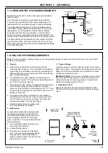


2.20 BOILER WATER CONNECTIONS
The boiler flow and return pipes are
terminated with a 1
1
/
4
” BSP male taper
connection located at the bottom of the
appliance.
Note.
This appliance is NOT suitable for use
with a direct hot water cylinder.
Plastic plugs if fitted into the open ends of
the flow and return pipes must be removed
before connecting the system pipework.
2.21 FROST PROTECTION
The boiler has built into its control system the facility to protect
the boiler, only against freezing.
If the boiler flow temperature T
1
, falls below 5
o
C the pump and
burner run until the temperature exceeds 19
o
C.
Central heating systems fitted wholly inside the building do
not normally require frost protections as the building acts as
a ‘storage heater’ and can normally be left at least 24 hours
without frost damage. However, if parts of the pipework run
outside the building or if the boiler will be left off for more than
a day or so, then a frost thermostat should be wired into the
system.
FLOW
RETURN
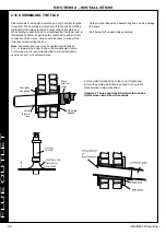
2.22 GAS CONNECTION
Refer to Section 1.13 for details of the position of
the gas connection.
A MINIMUM working gas pressure of 17.5 mbar
(7” w.g.) must be available at the boiler inlet for
natural gas and minimum of 32mbar for propane
with the boiler firing. Refer to Section 3.3 for
details of the pressure test point position.
Extend a gas supply pipe NOT LESS THAN 22mm
O.D. to the boiler and connect using the gas cock
provided.
IMPORTANT
. The gas service cock contains a
non-metallic seal so must not be overheated when
making capillary connections.
The pressure loss for LPG versions is negligible due to the very low
velocity through the pipe work.
Note.
It should be noted that this pressure drop is present within the
internal boiler pipe work and is irrespective of the fact that manifold
headers are used. This pressure drop will be experienced on each
individual boiler regardless of single or multiple installation.
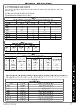
In order to determine the actual working gas pressure at the
boiler inlet the figure from the table below must be added to the
measured pressure (refer to Section 3.3).
Gas Line Pressure Drop
(Natural Gas)
Boiler Model
mbar
30
0.6
40
0.8
60
1.4
80
1.6
100
1.1
120
2.7
150
3.0
27
Installation & Servicing
SECTION 2 - INSTALLATION
INST
ALLA
TION
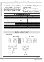
Summary of Contents for EVOMAX 2 30
Page 4: ...4 Installation Servicing...
Page 75: ...75 Installation Servicing NOTES...
Page 76: ...76 Installation Servicing NOTES...
Page 77: ...77 Installation Servicing NOTES...
Page 78: ...78 Installation Servicing NOTES...