10
Classic LX, RS -
Installation
INSTALLATION
INST
ALLA
TION
4
UNPACKING
The boiler is supplied fully assembled in Pack A, together with a
standard flue assembly for lengths up to 305mm (12") in Pack B.
Optional extras, if ordered (Programmer Kit, Sealed System Unit
and Extension Duct Kit 'D') are available in separate boxes.
Unpack and check the contents.
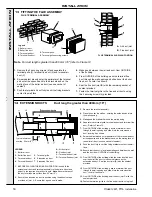
FLUE PACKS
Note.
All flue packs contain 2 sachets of sealant
PACK B
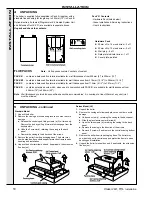
- contains a balanced flue terminal suitable for wall thicknesses from 229mm (9") to 305mm (12")
PACK B1
- contains a balanced flue terminal suitable for wall thicknesses from 318mm (12
1/2
") to 394mm (15
1/2
")
PACK C
- contains a balanced flue terminal suitable for wall thicknesses from 114mm (4
1/2
") to 191mm (7
1/2
")
PACK D
- contains extension ducts which, when used in conjunction with PACK B, are suitable for wall thicknesses from
406mm (16") to 584mm (23").
Note.
Wall thicknesses outside those specified cannot be accommodated. An overlap of at least 50mm at any duct joint
must be allowed.
Hardware Pack
z
50mm x No. 14 wood screw - 3 off
z
50mm x No. 10 wood screw - 3 off
z
Wall plug - 6 off
z
Data plate indicator arrow - 1 off
z
Cover plate, painted
5
UNPACKING - continued
Standard Model
1.
Unpack the boiler
2.
Remove the casing as follows and place to one side to avoid
damage.
a.
Release the controls pod fixing screws (a) 3 full turns only.
Remove the pod by pulling it forward to disengage from the
keyhole slots.
b.
Undo the 3 screws (b), retaining the casing to the back
panel.
c.
Remove the casing in the direction of the arrows.
3.
Remove the boiler from its packaging base. The boiler may
now be stood on its controls support protection frame to ease
handling and installation
4.
Unpack the boiler terminal box and, if applicable, the extension
flue box(es).
Deluxe Model (LX)
1.
Unpack the boiler
2.
Remove the casing as follows and place to one side to avoid
damage.
a.
Undo one screw (c), retaining the casing to the back panel.
b.
Slide the glass fascia upward (arrow d)
c.
Undo the two screws (e), retaining the casing to the back
panel.
d.
Remove the casing in the direction of the arrows.
e.
Remove 2 screws (f) and remove the controls casing bottom
panel.
3.
Remove the boiler from its packaging base. The boiler may
now be stood on its controls support protection frame to ease
handling and installation
4.
Unpack the boiler terminal box and, if applicable, the extension
flue box(es).
Pack 'A' Contents
- Hardware Pack (listed below)
- these Installation & Servicing Instructions
- User's Instructions.
Summary of Contents for Classic LXRS 230
Page 1: ......


