IDEAL INDUSTRIES UniPRO MGig1 User Manual Download Page 7


UniPRO 


152810 

User Guide 


Page 7 


Power 

UniPRO MGig1 can be powered from: 

  A rechargeable battery pack, 

  AA alkaline batteries (not supplied) in an optional holder, 

  Directly from power connected to the DC inlet. 


UniPRO SEL1 can be powered from: 

  A rechargeable power module, 

  AA alkaline batteries (not supplied) in an optional holder, 

  Directly from power connected to the DC inlet built in to the power module. 


Power Management, battery pack and power module 

A fully charged battery pack or power module will support up to five hours of heavy, continuous use of a 

single port, or 3.5 hours continuous use of two ports.  For maximum life of the unit, it is recommended to 

discharge it fully and then recharge it fully at least once a month. 

The rechargeable battery pack and the power module are not user-serviceable.  When they have reached 

the end of their life, contact your local IDEAL representative for service. 


Battery Pack and Power Module Recharging 

The battery pack or power module can be fully recharged in three hours with the handset switched ON or 

OFF.    To  recharge,  connect  the  supplied  power  adaptor  to  the  DC  inlet.    For  convenience  the  power 

module may be removed from, or left attached to, the UniPRO SEL1  for charging.  The Power LED next 

to the DC inlet glows green to show that the battery is being charged, and flashes green to show that it is 

not being charged. 

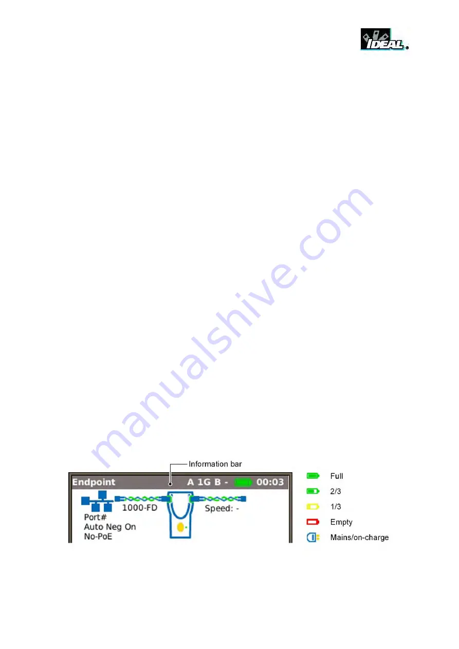
The  UniPRO  MGig1’s  battery  pack  charge  state  is  indicated  at  FULL,  2/3,  1/3  and  EMPTY  by  the 

graphical power meter shown in the display’s information bar at the top of its LCD display. 


Fig 2  Power indications 

Summary of Contents for UniPRO MGig1

Page 1: ...UniPRO MGig1 User Guide 152810 Iss 1 UniPRO SEL1 ...

Page 2: ... on reproduction and use apply to all media in which this information may be placed IDEAL INDUSTRIES Ltd pursues a policy of continual product improvement and reserves the right to alter without notice the specification design price or conditions of supply of any product or service IDEAL INDUSTRIES LTD 2013 All rights reserved Publication ref 152810 Issue 1 05 13 Applies to software revision 0 0 7...

Page 3: ...2 MGig1 12 SEL1 13 Transmission testing concepts 14 General 14 Ethernet frame structure and Layers 15 Loopback and Layers 16 Connection Establishment 18 Targets and Services 18 Traffic Impairments 19 Ethernet transmission testing methods 19 BERT 19 SLA Tick 19 RFC2544 19 Y 1564 NetSAM 20 Modes of Operation 21 Endpoint 21 Through 21 Ports 22 Setup 23 Targets 24 Services 26 Test data Error inject 27...

Page 4: ...e Job 57 Managing Jobs 58 Generating Reports 59 MGig1 software updates and configuration 59 SEL1 software updates and configuration 60 General 60 Update software 60 Upload configuration for transfer to other SEL1 handsets 60 Download configuration 60 Reset SEL1 to factory default 60 Specifications UniPRO MGig1 61 Glossary abbreviations and acronyms 63 ...

Page 5: ...EL1 Fig 1 UniPRO handsets The MGig1 is available in the variants that follow and with the features indicated MGig1 MGig1 PLUS MGig1 PRO Copper port Optical port Multi service Bidirectional Y 1564 MPLS VLAN Levels 3 3 8 The range listed above is also available in Duo format which adds a second copper and optical port making a total of six MGig1 variants The additional ports extend functionality to ...

Page 6: ... life you must dispose of the complete unit in accordance with local environmental regulations Safety Information When using UniPRO handset always take basic safety precautions to reduce the risk of fire electric shock and injury to persons These precautions include When connecting to the line special care must be taken as high voltages may be present on the line and there may be a danger of elect...

Page 7: ... recharge it fully at least once a month The rechargeable battery pack and the power module are not user serviceable When they have reached the end of their life contact your local IDEAL representative for service Battery Pack and Power Module Recharging The battery pack or power module can be fully recharged in three hours with the handset switched ON or OFF To recharge connect the supplied power...

Page 8: ...F either unit before removing the battery pack or power module CAUTION EQUIPMENT DAMAGE Do NOT remove the battery pack or power module when the unit is switched on Power Saving UniPRO MGig1 has power saving preferences that are selected from SETUP SYSTEM PREF Auto Off can be Disabled unit remains ON indefinitely or set to switch the unit OFF after three 10 or 30 minutes of inactivity The backlight...

Page 9: ...to the socket with your finger until it is secure Fig 4C Fig 4 Functional overview The MGig1 range offers six models The available functions are listed below The information throughout this publication details the functions available to MGig1 Duo PRO Please check this table to confirm the functions available on your tester Function MGig1 Solo MGig1 Solo PLUS MGig1 Solo PRO MGig1 Duo MGig1 Duo PLUS...

Page 10: ...key 2 2 RJ 45 activity LED 7 Autotest button 12 Cursor and ENTER keys 3 2 RJ 45 link LED 8 USB port 13 Charger LED 4 1 2 Optical port SFP 9 LCD color display 14 ON OFF button 5 1 2 Optical activity LED 10 Function keys F1 to F4 15 DC in connector Fig 5 1 Fig 5 items 4 5 6 MGig1 PLUS PRO models only 2 Fig 5 items 1 to 6 on right hand view MGig1 Duo models only ...

Page 11: ...2 RJ 45 activity LED 11 Layer 1 Regenerate LED 3 RJ 45 link LED 12 Layer 1 Physical LED 4 Optical port SFP 13 Layer button 5 Optical activity LED 14 Power status indicator LED 6 Optical link LED 15 ON OFF button 7 USB port 16 Power module 8 Layer 4 LED 17 Charger LED 9 Layer 3 LED 18 DC in indicator Fig 6 ...

Page 12: ...nus that appear on the display ENTER selects the currently highlighted option Escape key Returns to previous screen or hides the options of a drop down menu Note that when a value in a settings field is changed if the Escape key is pressed before the soft key APPLY the value will not be stored Autotest key Immediately runs pre stored tests A new tester will have factory stored tests in memory Thes...

Page 13: ... above the keyboard Key stroke errors are corrected using the backspace key Press the UP cursor key to move the cursor into the text window for editing Press the QWERTY keyboard s SHIFT key to change the display from lower to upper case Press SHIFT a second time to display symbols and punctuation characters SEL1 Press the blue Layer button on the front of the handset to cycle through all loop opti...

Page 14: ... very easy to set up A loopback device such as SEL1 can be installed at the remote end of the transmission loop with minimum skill requirements and can be controlled by the tester at the local end Alternatively the sending device and the checking device may be in different locations Fig 12 Bi Directional test method Unlike the loopback method bi directional tests confirm the direction as well as t...

Page 15: ... and not through switches or routers Layer 1 frames do not have the ability to check frame errors Fig 13 Layer 1 Frame Layer 2 frames have a Destination and Source MAC address added that follows the SFD The MAC addresses enable the frames to be sent to a specific destination through Layer 2 switches Layer 2 frames may also have VLAN and or MPLS tags added after the source MAC sometimes this is cal...

Page 16: ... with no active network elements Layer 1 Regenerate Loop Errored frames are dropped Good frames are retransmitted exactly as received To determine if a frame contains an error it is necessary to receive and check the complete frame before it is retransmitted This introduces at least one frame of delay in the retransmission Therefore the loopback operation introduces some latency that must be allow...

Page 17: ...e used over a a physical connection or b over a switched network using Layer 2 or Layer 3 switching or c over a routed network Fig 18 Layer 3 Loop Layer 4 UDP Good frames are retransmitted and altered so that the Source and Destination MAC addresses and the Source and Destination IP addresses are swapped as at Layer 3 In addition this loop type swaps the UDP Source and Destination Port numbers so ...

Page 18: ...have the public IP address of the edge router in their Destination fields and in addition the port number of the port to which the target is connected The router will need to be set up with port forwarding to forward the frames to the target using the correct port number The frames retransmitted by the loopback device will have the LAN address of the router in their destination field This will be ...

Page 19: ...mes and checking them bit by bit at the receiver Individual bit errors are counted and expressed as a ratio to the total data received and periods of time during which the error ratio exceeds pre defined limits are recorded Errors of different types can be forced into the frames or the payload data in order to confirm that the error checking mechanism is working correctly and to determine how the ...

Page 20: ...a condition in which they are ready to transmit traffic again For each frame size the System recovery sub test generates traffic at the rate found by the Throughput sub test and measures the recovery time of the network Y 1564 NetSAM In an attempt to overcome some of the limitations of RFC2544 notably the long test times the sequential nature of the tests and the unrealistic single service traffic...

Page 21: ...ls are run Fig 20A Before a transmission test is run a far end loopback must be set Configuration of a SEL1 handset that has been discovered as a target can be set remotely from the MGig1 see page 29 A B Fig 20 Through mode Fig 21 Through mode is for viewing statistics Select PORTS and choose Through Mode from the dropdown menu and select APPLY F3 MGig1 will detect the connected services and show ...

Page 22: ...rts copper or optical from the dropdown lists and press APPLY F3 Modes are explained on page 21 When you select APPLY F3 MGig1 detects connected services and shows them on the display Tick the check box to always see this screen at startup NOTE Fig 22 shows the Ports screen from the MGig1 Duo PRO Port and mode options are dependent on the model Fig 22 ...

Page 23: ... 27 Set addressing type Set level ID PCP Port settings inc max min frame size Set addressing type Port id and max min frame size Enter tester owner s details Page 56 Set language preference Set user preferences Set time and date Product information Update software Restore factory defaults Page 30 Page 30 Page 31 Page 31 Page 31 Set cable type NVP Set Loopback type Set IR frame size Profile for Tra...

Page 24: ...A Select ADD F1 and a pop up dialog gives you the choice of searching for IDEAL targets or to configure the search manually Select SEARCH from the pop up dialog and after a scan the Discover screen is shown on the display Fig 24B A B Fig 25 On the Discover screen highlight the target you wish to add and select SELECT F3 The new target screen appears Fig 25A where you can reconfigure some of the ne...

Page 25: ...H LEDS F4 and the five Layer LEDs on the SEL1 handset will flash together This quickly enables you to physically identify the unit Fig 26 To delete a target from the Targets list use the tester s arrow keys to highlight the device to be removed and then select DELETE F2 a pop up dialog asks for confirmation select Yes and the target is removed from the list To reconfigure a SEL1 target see Remote ...

Page 26: ... Allocate a name to each service when required E g CCTV Email Video etc Protocol Choose from TCP UDP ICMP IP Set source destination as local from target or define your own When you define your own destination Custom it overrides the target selected in a test When required each service may be set with a different address i e eight separate targets You must manually enter the address for each MPLS E...

Page 27: ...ern errors is to confirm that the tester is counting bit errors correctly e g if two errors are injected two should be recorded Oversize or Undersize will inject frames of a size that is one byte greater than the maximum or one byte less than the minimum set in SETUP NET RJ45 Errors Single or Ratio Select Single and while a test runs each time you press INJECT F3 Fig 29 one error is injected Selec...

Page 28: ...configure the search manually Select SEARCH from the pop up dialog and after a scan the Discover screen is shown on the display Highlight the MGig1 Slave and select SELECT F3 The Target screen is shown on the display Select APPLY F3 and the tester returns to the Targets list which now includes the recently discovered MGig1 Fig 32 For Bi directional tests you must set the slave MGig1 to No Loop as ...

Page 29: ...e Targets list Select ADD F1 and a pop up dialog gives you the choice of searching for IDEAL targets or configure the search manually Select SEARCH from the pop up dialog and after a scan the Discover screen is shown on the display highlight the additional SEL1 and select SELECT F3 A new target screen appears where you can reconfigure some of the new target s details before you add it to the targe...

Page 30: ... the IPv4 or v6 TARGET look up table or edit the URL currently shown on the display Count Number of times to repeat the Ping 1 to 999999 Pause Interval between successive Pings 1 to 5 seconds Length Number of bytes in Ping frame payload 8 to 1000 bytes Fig 38 The results of a ping test are shown in Fig 38 The range of possible results are Info READY IN PROGRESS PASSED NETWORK UNREACHABLE UNKNOWN H...

Page 31: ...e recorded during each trace is shown on the display in ms as T1 T2 and T3 PoE When MGig1 is connected to a port it automatically detects PoE voltage when present In addition running a PoE test will apply a resistive load and measure the power available at the connected port MGig1 identifies which pairs are carrying power and displays the voltage V current mA and power W The PoE test result screen...

Page 32: ... a network device to blink MGig1 also changes the speed and therefore LED color on supporting devices making it easier to identify the correct port Select the BLINK icon from the Tests screen the test is started and stopped with the soft key F1 which displays as RUN or STOP accordingly ...

Page 33: ...ice takes and the information rate frame size and fill To adjust the settings for each of the eight services select the Service 1 to 8 and the Limits screen for that service is shown on the display Fig 42 Info Rate Enter a value in Mb s MGig1 will calculate the maximum info rate per service based on the info rate of other services and the frame size You may enter less than the maximum When Service...

Page 34: ...p set from 1 to 1 000 000 µs interval between steps Steps set from 1 to 10 000 No of steps Step Size set from 1 to 1 000 000 frames Because the Step Size is set as a number of frames rather than a time period the ramp profile is non linear If the Stop Info Rate is higher than the Start Info rate the ramp increases the Info rate over time If the Stop Info Rate is lower than the Start Info rate the ...

Page 35: ...ay NOTE MGig1 Duo models have TOOLS A or TOOLS B choose whether to generate traffic on the primary A or secondary B ports A B Fig 43 From the Traffic screen Fig 43A select RUN F1 to start generating traffic The Traffic Generation Utilization Plot will indicate the bandwidth utilization for each service Fig 43B Select MORE F2 to display the same data as a table ...

Page 36: ...Service BERT runs on one service only Choose a service from the dropdown list Note that when the service selected has been setup with a Custom target via SETUP SERVICES different to that chosen from the Target list above then the target associated to the service will be used Test pattern Choose one of the test patterns from the dropdown list to fill the payload When the Word pattern is selected en...

Page 37: ...ration Each error sync loss will cause the counter to stop until sync is regained Err Time is the time that the BERT pattern was out of sync since the start of the test expressed as both a percentage of the test duration and in hours minutes and seconds Sync Losses Number of times the pattern has gone out of sync Fig 45 Fig 46 Rx Sync bits Number of received bits that have remained in sync express...

Page 38: ...ore it starts the next sub test Fig 47 For each Service that you wish to use proceed as follows Select the service e g Service 1 the Limits screen is shown on the display Fig 48 A B Enter the Info Rate Frame Size and Pattern Data As you set the Info Rate both the percentage used by that service Bandwidth Utilization and the percentage that remains available for other services are shown Bandwidth U...

Page 39: ... Select the buttons shown on screen B and test results are shown on the display as a series of graphs and tables MORE F2 toggles between the two screens A B Fig 49 SLA Frame Error Rx Tx Frame Counts Rx Tx Layer Payload Rx Frame Size Rx Frame Types Rx Errors and Rx Errored Time are shown as tables only all other results are shown as tables and graphs For each of the graphs Latency results are shown...

Page 40: ...ecimal characters Direction is reported as Single Ended or Bidirectional dependent on whether a second MGig1 is selected as the target Select PROFILE F2 to set the test to Super Fast Fast or Full Select MORE F1 Fig 52 and tick the check boxes against the subtests you require throughput must be selected Select F4 to choose between SINGLE Single Ended loopback or BIDIR Master to Slave and Slave to M...

Page 41: ...44 test can be run From the home screen select TESTS RFC2544 The RFC2544 screen is shown on the display Fig 54 Fig 54 The Service Target and Direction that you have entered at set up are listed The Direction is determined by the target If target is MGig1 Slave then Bidirectional will be selected otherwise single ended will be selected The estimated duration is shown as a range in hours minutes and...

Page 42: ...t is calculated to within the specified Resolution 0 to 50 Fig 55A The Duration can be set from 1 to 300 seconds it is the period that each batch of frames is sent for Set the percentage of lost frames that is acceptable for the test in Max Frames Lost Set from 0 to 10 A B Fig 55 Choose the frame size s and throughput rate limit see Fig 55B Tick the checkbox adjacent to the frame sizes you require...

Page 43: ...A B Fig 57 The throughput test will determine the throughput rate for the latency test Set the Repetitions 1 to 100 and the Duration 1 to 300 seconds Select MORE F1 and tick the check boxes next to the frame sizes required for the test Against each frame size set the Latency Limit in µs 0 to 10 000 000 MGig1 presents Latency results as a graph that plots time µs against Frame size and a table that...

Page 44: ...sizes selected at set up Set the number of Repetitions 1 to 10 to test the network for Jitter and the Duration 1 to 300 seconds for each repetition Fig 59A Select MORE F1 and tick the check boxes next to the frame sizes required for the test Fig 59B Against each frame size set the Jitter Limit in µs 0 to 2 000 000 Results are provided as a graph that plots jitter in µs against frame sizes and as a...

Page 45: ...space between steps in utilization Duration 1 to 300 seconds The period for which frames are transmitted Fig 61 Fig 62 The frame loss test presents results as a graph that plots percentage Frame Loss against percentage Frame Rate Fig 62 The function key F3 toggles between the graph and a table that lists percentage frame loss for each frame size at different network utilizations The table is displ...

Page 46: ...m and maximum number of frames in each burst is specified at the Back to Back set up screen Fig 64 Min Burst and Max Burst are the minimum and maximum number of frames in each burst Repetitions is the number of times that a series of bursts are sent Resolution is a percentage of the specified number of frames The range for each variable is as follows Min Burst 1 to 1 000 000 000 frames Max Burst 1...

Page 47: ...rames Then the traffic is reduced to less than the pre determined throughput The time between the drop in frame rate to the last lost frame is averaged over a user specified number of test runs for each frame size The range for each variable is as follows Repetitions 1 to 100 The number of test runs Duration 1 to 300 Period in seconds that excess traffic is generated Fig 66 Fig 67 MGig1 presents t...

Page 48: ...eria above MORE F1 scrolls through the criteria As up to eight services can be used within each sub test the soft keys NEXT and PREV are used to navigate between results for all services tested When errors in network configuration are identified they must be corrected and verified before performance tests are run In addition to the four configuration test criteria the performance test measures Net...

Page 49: ...is greater than the CIR the test is passed C1 Police Color The C1 Police Color test checks that the network drops frames transmitted at a rate greater than the EIR The method is to transmit frames marked green at a rate equal to the CIR and frames marked yellow at a rate of 125 EIR All frames are transmitted at constant intervals If the FLR FTD and FDV for the green marked frames are all within th...

Page 50: ...5 15 30 secs or user defined up to 24 hours A2 Set step sizes to 10 20 25 or 50 of the CIR and set the duration to transmit at each step from 1 to 60secs B1 B2 Select duration from 5 15 30 secs or user defined up to 24 hours C1 C2 Select duration from 5 15 30 secs or user defined up to 24 hours and Fig 69 Set M Factor in Mb s The M Factor is a value in Mb s that is added to the IR to allow for the...

Page 51: ...te designators CIR Set CIR for the service EIR Set EIR for the service Values entered here are ignored for subtests A1 A2 Pattern Data Enter up to eight hexadecimal characters Color Mode screen Select the Color Mode from the drop down list IP VLAN or MPLS dependent on where network priority for EIR should be Now set a value for both the Green and Yellow indicators by selecting the data entry box n...

Page 52: ...n a separate row This test was setup with steps set at 10 CIR therefore there are 10 steps scroll down to see the last five The results shown are for Service 1 indicated by S 1 on the screen Select NEXT F4 to view the other services tested Select MORE F1 to view the Frame Loss Frame Transfer Delay and Frame Delay Variation Fig 74 Fig 75 Performance is checked on all services simultaneously and the...

Page 53: ...your choice Fig 78 refers Select APPLY F3 to save your choices and a screen showing the selected tests is shown on the display with a ready symbol adjacent to each test Fig 79 Fig 78 Fig 79 Select RUN F1 and the tests will start MGig1 will decide in which order to run the tests When all tests are complete select any of the tests from the screen to view the results To save the results press the Esc...

Page 54: ...ed and started for each of the individual tests Transmission statistics are available from within RFC2544 NetSAM and SLA Tick tests Fig 80 Stats menu description For each port only Duo models have a B port select from the three buttons on the Stats screen to provide the information that follows IP The F1 soft key is used to toggle between IPv4 and Ipv6 data The IPv4 data listed is Info IP Assigned...

Page 55: ...applies to both RJ45 and Optical ports Jabbers Bad Length Partner data listed is 10M HD 10M FD 100M HD 100M FD 1000M HD 1000M FD From the home screen in Through mode select the STATS icon the Stats screen is shown on the display Fig 81 A graph shows Traffic Utilization and utilization against time Select SCALE F2 to change the time axis between 60secs 10mins and 60mins For Duo models select the F3...

Page 56: ...y active Job is indicated in the information bar shown at the top of the display Every time test results are saved they are saved to a Result which is assigned a sequential number In turn each Result is allocated to the currently active Job The structure in which Jobs Results and test results are stored is shown in Fig 82 Fig 82 Example of Job storage structure When creating a new Job you can stor...

Page 57: ...ig 83 Job List screen Change the active Job In the example of a Job List screen shown at Fig 83 the active Job is Acme as indicated on the display s information bar To change the active Job scroll to the Job required e g My Job and select OPTIONS F2 the display will show the Options screen Fig 84 Select the ACTIVATE icon Fig 84 Options screen The display will show a dialogue stating MyJob is set a...

Page 58: ...not shown on the Options screen An existing Job must be deleted for the NEW icon to reappear Amend any details of an existing Job Select APPLY F3 to save the changes Delete a Job and all its associated Results When DELETE is selected the dialogue Are you sure you want to delete Job will appear once deleted a job cannot be restored Selects the Job to be currently active All test results are saved t...

Page 59: ...tistics are now saved on the USB key and can be viewed as a report on any PC installed with Microsoft Internet Explorer Mozilla Firefox or other suitable browser Files are saved to the USB key the test results are stored as an XML document and a report template is stored as an XSLT file Open the XML document to view the report MGig1 software updates and configuration Update software To update the ...

Page 60: ...into the USB socket item 7 at the top of the SEL1 handset Press and hold down the blue Layer button item 13 With the blue Layer button held down press the ON OFF button 15 until the LEDs glow Release both buttons The LEDs will flash for a brief period When they stop remove the flash drive from the USB port The configuration is saved to the root directory of the flash drive and ready for download t...

Page 61: ...n on PRBS ITU or Non ITU 2n 1 n 11 15 20 23 31 SCRTPAT CRPAT CJTPAT CSPAT LFPAT HFPAT MFPAT fixed all 1s 0s 1100 1000 1010 Word 4 digit Hex Control manual or user defined duration Error injection single rate on frame or bit Multi services streams Up to eight services simultaneously generated and measured on FLR FTD FDV IR with independent IP MAC VLAN MPLS TCP or UDP ports setup on each service for...

Page 62: ...sers Storage Internal configuration profile MGig1 30 SEL1 1 Internal reports 250 MGig1 only Format xml External storage USB Display 3 5 TFT color touch screen UniPRO MGig1 5 LEDs UniPRO SEL1 Battery NiMH Rechargeable auto power off 3 10 30 min MGig1 continuous use 4hrs MGig1 3 5hrs SEL1 power adaptor 100 240VAC IN 12VDC OUT System interface USB 1 1 for external storage on software upgrade test rep...

Page 63: ...ly Noise Data Pattern A special purpose test data pattern DHCP Dynamic Host Configuration Protocol Discovery data LLDP Link Layer Discovery Protocol CDP Cisco Discovery Protocol EDP Extreme Discovery Protocol DNS Domain Name System EBS Excess Burst Size EIR Excess Information Rate Errored Second Any second containing one or more lost or errored frames Errored Time Number of Errored Seconds express...

Page 64: ...ludes the SFD the Preamble and the IFG parts of the Ethernet structure Layer 1 Payload Everything in the Ethernet frame between but not including the SFD and the IFG Includes the MAC and the FCS Layer 2 L2 The Data link layer of the ISO 7 layer model Includes the MAC and FCS parts of the Ethernet frame Layer 2 Payload Everything in the Ethernet frame between but not including the MAC and the FCS L...

Page 65: ...witching protocol MTU Maximum Transmission Unit Multicast Communication between single sender and multiple receivers NetSAM IDEAL INDUSTRIES special name for Y 1564 NVP Nominal Velocity of Propagation of signals in a cable expressed as a percentage of the speed of light in a vacuum Can be determined using cable manufacturers data or experimentally using a known cable length PCP Priority Code Point...

Page 66: ...trol TTL Time To Live Limits the lifetime of stray Ethernet frames to avoid build up in networks Tx Transmit UDP User Datagram Protocol Unavailable Time Any period of ten seconds or more during which every second is a Severely Errored Second Unicast Communication between single sender and single receiver URL Uniform Resource Locator USB Universal Serial Bus Utilization The ratio of Information Rat...

Page 67: ......

Page 68: ...A subsidiary of IDEAL INDUSTRIES INC ...

Reviews: