52
Installation and Servicing
SECTION 3 - SERVICING
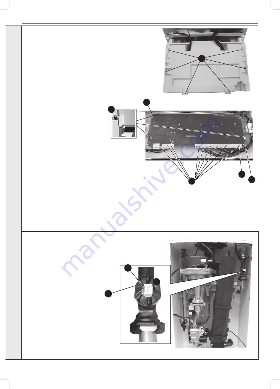
3.18 PCB REPLACEMENT
Note.
Fit the earth strap provided with the PCB to your wrist and
secure to a suitable earth on the boiler chassis.
1.
Refer to Section 3.8.
2.
Ensure the control knobs are in the 12 o clock position.
3.
Carefully release the six retaining clips and remove control
box cover.
4.
Unplug all lead connections to the PCB.
5.
Remove the 2 screws, if applicable.
6.
Spring out the four side retaining clips and pull the PCB
upwards to clear the corner retaining posts.
7.
Take the new PCB.
8.
Re-connect all plug connections.
9.
Reassemble in reverse order.
10.
a. Turn power on, display shows uP.
Rotate both dials fully
anti-clockwise.
b. Press
RESTART, display shows oF
c. Turn power off
d. Turn power on, display shows F9
e. Using central heating knob, rotate clockwise or
anticlockwise to show “H” for Heat, then press
RESTART button.
f. Using central heating knob, rotate clockwise or
anticlockwise to show “n” for Natural Gas, then press
the RESTART button.
g. Using central heating knob rotate clockwise or
anticlockwise to show boiler size, select correct 12, 15,
18, 24 or 30, then press RESTART button.
h. Display shows “H”, “n”, Boiler size, internal number.
j. Press restart. New PCB is now programmed.
11.
Check operation of the boiler.
Refer to Sections 2.26 & 2.27.
3
IMPORTANT.
IT IS CRITICAL FOR SAFE
OPERATION THAT THE CORRECT BOILER SIZE
AND FUEL TYPE IS ENTERED INTO THE BOILER.
3.19 WATER FLOW SWITCH HEAD REPLACEMENT
1.
Refer to Section 3.8.
2.
Drain the Boiler. Refer to Section 3.20,
item no. 2.
3.
Pull off the electrical connection.
4.
Turn the retaining collar anti-clockwise and
pull the head from the housing.
5.
Fit the new water flow switch head,
ensuring the electrical lead connections
wires point to the left as shown.
6.
Re-assemble in reverse order.
7.
Re-fill the boiler.
8.
Check the operation of the boiler.
Refer to Sections 2.26 & 2.27.
3
4
5
SER
VICING
6
4
4
5
5
Summary of Contents for LOGIC MAX HEAT H 12
Page 4: ...4 Installation and Servicing ...
Page 6: ...6 Installation and Servicing ...
Page 61: ...61 NOTES Installation and Servicing ...
Page 62: ...62 Installation and Servicing SECTION 5 SPARE PARTS ...
Page 68: ...68 NOTES Installation and Servicing ...


