background image

WEBLINK REFERENCE

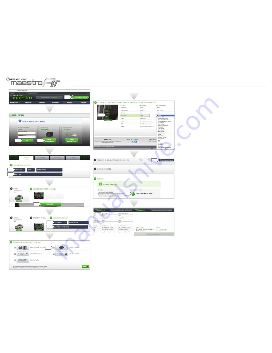
Visit  maestro.idatalink.com  and  click  on  FLASH  YOUR 

MODULE to access the WEBLINK menu.

Log in if you are already registered.

Create an account if you are not registered.

Select your vehicle’s make, year and model.

Select  your  vehicle’s  factory  radio  trim.  This  is  not  to  be 

confused  with  the  aftermarket  radio  that  you  are  about  to 

install.

Select  the  steering  wheel  that  matches  the  one  in  your 

vehicle.  Only  the  radio  related  control  buttons  must  match. 

Cruise  control  buttons  and  other  kinds  of  buttons  are  not 

important.  If  you  choose  a  non  matching  steering  wheel, 

some SYNC features may not work.

Select the brand and the model of the aftermarket radio that 

you are about to install.

This menu will not appear if the radio is not compatible. If the 

menu select connection type appears, choose iDatalink serial 

cable.  It  will  offer  you  all  the  data  features  on  compatible 

radios.  (The  wired  remote  input  will  only  offer  basic  analog 

features.)  After  choosing  iDatalink  serial  cable,  enter  the 

radio serial number.

On this screen, check the boxes next to the features you wish 

to  retain  and  uncheck  the  ones  you  want  to  remove.  If  a 

feature is grayed out, it cannot be retained with the current 

selection.  Click  on  the  feature  to  see  how  to  retain  it.  If  a 

feature  is  not  shown,  it  is  not  available  for  the  selected 

vehicle.

If the vehicle is equipped with a Sony or THX system and you 

are planning to use an aftermarket speaker amplifier instead 

of the factory speaker amplifier  you must uncheck the factory 

amplifier option for the fader and balance to work.

Click to change the functions of your steering wheel buttons.

If a function is not shown in the drop down menu, it means 

that it’s not supported by the radio.

Click to view and print your wallet card. 

Click to see your install guide.

This is a wallet card example.

1-

2-

3-

4-

5-

6-

7-

8-

9-

10-

11-

12-

13-

14-

1

2

4

5

6

12

10

11

13

14

7

9

8

3

maestro.idatalink.com

Automotive Data Solutions Inc. © 2013

ADS-RR(SR)-FOR01-DS2TH-IG-EN

PAGE 3 OF 6

• 20130924

Summary of Contents for maestro Rr ADS-RR-FOR01-DS-IG-EN

Page 1: ...erly trained technicians a certain level of skill knowledge is therefore assumed Please review the Installation Guide carefully before beginning any work BEFORE INSTALLATION 1 Connect the module to co...

Page 2: ...COM FUSED V 600V CAT IV 1000V CAT III V DC 02 03 04 05 SUGGESTED TOOLS Multimeter Soldering iron and solder Wire cutter Wire stripper Electrical tape www maestro idatalink com Automotive Data Solutio...

Page 3: ...BROWN LEFT 2 AUDIO INPUT 09 PURPLE RED RIGHT 2 AUDIO INPUT 10 PURPLE BROWN RIGHT 2 AUDIO INPUT BLACK WHITE 18 BLACK WHITE SWI GROUND FEED OUTPUT ORANGE RED 17 ORANGE RED SWI CIRCUIT 3 INPUT LTGREEN Y...

Page 4: ...tion 10 1 Escape 08 12 1 Expedition 07 09 1 Expedition without Navigation 10 1 Expedition with Navigation 10 1 Expedition 11 12 1 Explorer Sport Trac 06 09 1 Explorer Sport Trac without Navigation 10...

Page 5: ...S 09 12 1 MKT 10 12 1 MKX 07 09 1 MKX without Navigation 10 1 MKX with Navigation 10 1 MKZ 07 08 1 MKZ 09 12 1 Navigator 07 09 1 Navigator without Navigation 10 1 Navigator with Navigation 10 1 Naviga...

Page 6: ...0 41 42 43 44 45 01 02 03 04 05 06 07 08 09 10 11 12 13 14 15 16 17 18 19 20 21 22 23 24 25 26 27 28 29 30 31 32 33 34 35 36 37 38 39 40 41 42 43 44 45 x z A AA BB CC DD EE FF GG HH II JJ KK LL MM NN...

Page 7: ...White 24 pin 05 Yellow Green Radio 17 K JJ LF Speaker High Level FRD24 White 24 pin 08 White Radio 17 K JJ LF Speaker High Level FRD24 White 24 pin 21 White Brown Radio 17 K JJ RF Speaker High Level F...

Page 8: ...12V FRD24 White 24 pin 05 Yellow Green Radio 17 K JJ LF Speaker High Level FRD24 White 24 pin 08 White Radio 17 K JJ LF Speaker High Level FRD24 White 24 pin 21 White Brown Radio 17 K JJ RF Speaker Hi...

Page 9: ...12V FRD24 White 24 pin 05 Yellow Green Radio 17 K JJ LF Speaker High Level FRD24 White 24 pin 08 White Radio 17 K JJ LF Speaker High Level FRD24 White 24 pin 21 White Brown Radio 17 K JJ RF Speaker H...

Page 10: ...plified Antenna 12V FRD24 White 24 pin 05 Yellow Orange Radio 17 K JJ LF Speaker High Level FRD24 White 24 pin 08 White Radio 17 K JJ LF Speaker High Level FRD24 White 24 pin 21 White Brown Radio 17 K...

Page 11: ...08 pin 04 Violet Red Radio 17 K JJ LF Speaker High Level FRD24 White 24 pin 08 White Radio 17 K JJ LF Speaker High Level FRD24 White 24 pin 21 White Brown Radio 17 K JJ RF Speaker High Level FRD24 Wh...

Page 12: ...White 24 pin 05 Yellow Green Radio 17 K JJ LF Speaker High Level FRD24 White 24 pin 08 White Radio 17 K JJ LF Speaker High Level FRD24 White 24 pin 21 White Brown Radio 17 K JJ RF Speaker High Level...

Page 13: ...White 24 pin 21 White Brown Radio 17 K JJ RF Speaker High Level FRD24 White 24 pin 11 White Violet Radio 17 K JJ RF Speaker High Level FRD24 White 24 pin 12 White Orange Radio 17 K JJ LR Speaker High...

Page 14: ...FRD24 White 24 pin 05 Yellow Green Radio 17 K JJ LF Speaker High Level FRD24 White 24 pin 08 White Radio 17 K JJ LF Speaker High Level FRD24 White 24 pin 21 White Brown Radio 17 K JJ RF Speaker High...

Page 15: ...24 White 24 pin 21 White Brown Radio 17 K JJ RF Speaker High Level FRD24 White 24 pin 11 White Violet Radio 17 K JJ RF Speaker High Level FRD24 White 24 pin 12 White Orange Radio 17 K JJ LR Speaker Hi...

Page 16: ...range LtGreen Radio 17 K JJ LF Speaker High Level FRD24 White 24 pin 21 LtBlue White Radio 17 K JJ RF Speaker High Level FRD24 White 24 pin 11 White LtGreen Radio 17 K JJ RF Speaker High Level FRD24 W...

Page 17: ...tivation 12v FRD24 White 24 pin 05 Blue Radio 17 K JJ LF Speaker High Level FRD24 White 24 pin 08 White Radio 17 K JJ LF Speaker High Level FRD24 White 24 pin 21 White Brown Radio 17 K JJ RF Speaker H...

Page 18: ...12V FRD24 White 24 pin 05 Yellow Green Radio 17 K JJ LF Speaker High Level FRD24 White 24 pin 08 White Radio 17 K JJ LF Speaker High Level FRD24 White 24 pin 21 White Brown Radio 17 K JJ RF Speaker Hi...

Page 19: ...2V FRD24 White 24 pin 05 Yellow Green Radio 17 K JJ LF Speaker High Level FRD24 White 24 pin 08 White Radio 17 K JJ LF Speaker High Level FRD24 White 24 pin 21 White Brown Radio 17 K JJ RF Speaker Hig...

Page 20: ...Radio 17 K JJ Amplified Antenna 12V FRD24 White 24 pin 05 Yellow Green Radio 17 K JJ LF Speaker High Level FRD24 White 24 pin 08 White Radio 17 K JJ LF Speaker High Level FRD24 White 24 pin 21 White B...

Page 21: ...a 12V FRD24 White 24 pin 05 Yellow Green Radio 17 K JJ LF Speaker High Level FRD24 White 24 pin 08 White Radio 17 K JJ LF Speaker High Level FRD24 White 24 pin 21 White Brown Radio 17 K JJ RF Speaker...

Page 22: ...Antenna 12V FRD24 White 24 pin 05 White Radio 17 K JJ LF Speaker High Level FRD24 White 24 pin 08 White Radio 17 K JJ LF Speaker High Level FRD24 White 24 pin 21 White Brown Radio 17 K JJ RF Speaker H...

Page 23: ...tenna 12V FRD24 White 24 pin 05 Orange Radio 17 K JJ LF Speaker High Level FRD24 White 24 pin 08 Green Radio 17 K JJ LF Speaker High Level FRD24 White 24 pin 21 White Brown Radio 17 K JJ RF Speaker Hi...

Page 24: ...nna 12V FRD24 White 24 pin 05 Yellow Green Radio 17 K JJ LF Speaker High Level FRD24 White 24 pin 08 White Radio 17 K JJ LF Speaker High Level FRD24 White 24 pin 21 White Brown Radio 17 K JJ RF Speake...

Page 25: ...5 Yellow Green Radio 17 K JJ LF Speaker High Level FRD24 White 24 pin 08 White Violet Radio 17 K JJ LF Speaker High Level FRD24 White 24 pin 21 White Borwn Radio 17 K JJ RF Speaker High Level FRD24 Wh...

Page 26: ...a 12V FRD24 White 24 pin 05 Yellow Orange Radio 17 K JJ LF Speaker High Level FRD24 White 24 pin 08 White Radio 17 K JJ LF Speaker High Level FRD24 White 24 pin 21 White Brown Radio 17 K JJ RF Speaker...

Page 27: ...let Radio 17 K JJ Amplified Antenna 12V FRD24 White 24 pin 05 Violet Black Radio 17 K JJ LF Speaker High Level FRD24 White 24 pin 08 White Radio 17 K JJ LF Speaker High Level FRD24 White 24 pin 21 Whi...

Page 28: ...ation 5V FRD8 White 08 pin 04 Pink Radio 17 K JJ Amplified Antenna 12V FRD24 White 24 pin 05 Yellow Green Radio 17 K JJ LF Speaker High Level FRD24 White 24 pin 08 White Radio 17 K JJ LF Speaker High...

Page 29: ...ed Antenna 12V FRD24 White 24 pin 05 Yellow Green Radio 17 K JJ LF Speaker High Level FRD24 White 24 pin 08 White Radio 17 K JJ LF Speaker High Level FRD24 White 24 pin 21 White Brown Radio 17 K JJ RF...

Page 30: ...12V FRD24 White 24 pin 05 Yellow Green Radio 17 K JJ LF Speaker High Level FRD24 White 24 pin 08 White Radio 17 K JJ LF Speaker High Level FRD24 White 24 pin 21 White Brown Radio 17 K JJ RF Speaker Hi...

Page 31: ...ange LtGreen Radio 17 K JJ LF Speaker High Level FRD24 White 24 pin 21 LtBlue White Radio 17 K JJ RF Speaker High Level FRD24 White 24 pin 11 White LtGreen Radio 17 K JJ RF Speaker High Level FRD24 Wh...

Page 32: ...04 Violet Red Radio 17 K JJ LF Speaker High Level FRD24 White 24 pin 08 White Radio 17 K JJ LF Speaker High Level FRD24 White 24 pin 21 White Brown Radio 17 K JJ RF Speaker High Level FRD24 White 24...

Page 33: ...2V FRD24 White 24 pin 05 Yellow Green Radio 17 K JJ LF Speaker High Level FRD24 White 24 pin 08 White Radio 17 K JJ LF Speaker High Level FRD24 White 24 pin 21 White Brown Radio 17 K JJ RF Speaker Hig...

Page 34: ...RMARKET RADIO CUT AND INSULATE WIRE IN SYNC HARNESS SEE CHART FOR COLOR AND LOCATION VEHICLE HARNESS BEHIND RADIO SYNC HARNESS VEHICLE WITHOUT SYNC ONLY AUX INPUT AUX INPUT CENTER INPUT IDATALINK RADI...

Page 35: ...INPUT 03 PINK RED SWI CIRCUIT 2 INPUT BROWN RED 07 BROWN RED CAN1H INPUT BROWN YELLOW 08 BROWN YELLOW CAN1L INPUT 01 ORANGE PARKING LIGHT OUTPUT 03 PURPLE WHITE REV LIGHT OUTPUT 02 EMPTY 04 BROWN NC...

Page 36: ...ess Next To Continue Locating Satellites NEXT 10 OFF ACC ON START 11 OFF ACC ON START _________________________________ 12 13 MODULE PROGRAMMING PROCEDURE Open driver door Insert key into ignition Tur...

Page 37: ...ld programming button and con nect all connectors to the module Wait LED will flash RED rapidly This may take up to 10 seconds Release programming button Wait LED will turn solid GREEN for 2 seconds M...

Page 38: ...cle itself or to the installed device ADS recommends having this installation performed by a certi ed technician Please review this guide carefully before beginning any work Logos and trademarks used...

Page 39: ...linkmaestro com register and complete the CONSUMER registration form You will receive a con rmation email Click on the included link to activate your Weblink account 3 PROGRAM FIRMWARE TO YOUR MAESTRO...

Page 40: ...red remote input will only offer basic analog features After choosing iDatalink serial cable enter the radio serial number On this screen check the boxes next to the features you wish to retain and un...

Page 41: ...nnect only the available connectors For example if the factory harness has two connectors connect only these two connectors STEP 4 Plug the aftermarket radio harnesses into the aftermarket radio Plug...

Page 42: ...PLE BLACK RR SPEAKER YELLOW 12V BLACK GROUND RED ACCESSORY BROWN NOT CONNECTED ORANGE PARKING LIGHT PURPLE WHITE REVERSE LIGHT PINK NOT CONNECTED LTGREEN E BRAKE BLUE WHITE AMP TURN ON MAIN HARNESS PU...

Page 43: ...r Blue MUX Sync unit behind the glove box Taurus 08 09 SWI 2 Gray Blue MUX Center console right side harness going to the back Taurus 10 12 SWI 2 Blue Orange MUX Center console right side harness goin...

Page 44: ...OD RADIO ECLIPSE RADIO SELECT RADIO BRAND AND CONNECT RADIO CONTROL CABLE ACCORDINGLY RADIO CONTROL CABLE WIRING DIAGRAM OR OR OR OR NOT CONNECTED NOT CONNECTED NOT CONNECTED NOT CONNECTED BLACK NOT C...

Page 45: ...e vehicle itself or to the installed device ADS recommends having this installation performed by a certified technician Please review this guide carefully before beginning any work Logos and trademark...

Page 46: ...WEBLINK ACCOUNT Go to idatalinkmaestro com register and complete the CONSUMER registration form You will receive a confirmation email Click on the included link to activate your Weblink account 3 PROG...

Page 47: ...red remote input will only offer basic analog features After choosing iDatalink serial cable enter the radio serial number On this screen check the boxes next to the features you wish to retain and un...

Page 48: ...e to the data port of the aftermarket radio Insert the Audio cable into the iDatalink 3 5 mm audio jack of the aftermarket radio Insert the RCA connectors into the aftermarket radio NOTES The RCA conn...

Page 49: ...R SPEAKER PURPLE BLACK RR SPEAKER YELLOW 12V BLACK GROUND RED ACCESSORY BROWN NOT CONNECTED ORANGE PARKING LIGHT PURPLE WHITE REVERSE LIGHT PINK NOT CONNECTED LTGREEN E BRAKE BLUE WHITE AMP TURN ON MA...

Page 50: ...ter console right side in front of the arm rest Mustang 07 14 SWI 2 Blue Orange or Blue MUX Sync unit behind the glove box Taurus Taurus X 08 12 SWI 2 Blue Orange MUX Center console right side harness...

Page 51: ...ce FOR01 Installation Harness FOR1 Kenwood radio Owner s Guide RETAINS STEERING WHEEL CONTROLS SYNC MEDIA PLAYER SYNC BLUETOOTH AND MORE NOTICE Automotive Data Solutions Inc ADS recommends having this...

Page 52: ...ndy as they cover all the functionality that the Maestro RR retains Please note that all the retained functionalities must be initially available in the vehicle 1 866 427 2999 support idatalink com ma...

Page 53: ...eering wheel buttons will work differently These two buttons cannot be re configured For steering wheel button operation when Sync is retained see table below Pressing and releasing the Voice button o...

Page 54: ...be turned ON in the initial settings in the Kenwood This setting can also be changed in the source setup menu If you choose to use Sync for phone calls your phone must be paired to the Sync system A s...

Page 55: ...SYNC MEDIA The Sync Media source will allow you to use the line in and USB If you access the Sync Media source by using the radio s touch screen it will go to whichever connection you used last You ca...

Page 56: ...already in your vehicle rather than installing an aftermarket tuner Your vehicle must be equipped with an external satellite tuner for it to be retained by the Maestro RR module If your vehicle does n...

Page 57: ...o select and configure gauges In some radios the gauge selection menu can be quickly accessed by pressing for two seconds the gauge you want to configure Gauges that are supported in your vehicle will...

Page 58: ...he vehicle such as battery voltage and open entry points If the Check Engine light is ON in the vehicle the CHECK ENGINE button will become active Press this button to see the active trouble codes and...

Page 59: ...vehicle speed exceeds 5 mph or 8 km h Clear DTCs Diagnostic Trouble Codes This button will only be highlighted if the check engine light in the vehicle is ON This item will clear the light Warning If...

Page 60: ...e module will communicate with the vehicle s OBD2 system unless it detects another device This may be a scan tool or aftermarket programmer connected to the vehicle Always Enabled The module will comm...

Page 61: ...e screen Climate Type Gives the choice of Manual Auto or Dual Zone Auto The vehicle must be equipped with the selected system to operate properly Heated Seats Turns ON or OFF the option to show and co...

Page 62: ...ACCESSOIAES connee ACCESSORIES...

Page 63: ......

Reviews: