background image

8

ENGLISH

EN

4.  Mount the suspension block using two threaded 

bolts M10x25 mm

5.  Attach the charging station to the pole by using 

two threaded bolts M10x25 mm

6. 

Attach  the  ground  wire  to  the  pole  by  using 
M4x12 mm screws and one M4 circuit ring

7.  Run  the  ground  cable  through  the  concrete 

base and the pedestal to the charging station

Fig. 1: Mounting cable cover

8.  Attach the cover plate to the pole using the anti-

theft bolt M8x16 mm (see Fig. 1)

9.  Fill the hole and pave the area
10.  Cover  the  area  afterwards  with  a  clean  trim


(e.g. tiles)

Attaching the suspension block

1. 

Insert appropriate wall plugs into the four holes 

2. 

Attach  the  suspension  block  on  the  lower  two 
holes with two screws on the wall

Preparation of the charging station   

Never let the front cover hang on the wiring of the 

LEDs and the display.

NOTICE

The white front cover of the charging station must 
be removed before installing. Proceed as follows: 

The  front  cover  is  firmly  attached  to  the  charging 
unit and is secured with two screws at the top and 

bottom.
1. 

Place the device on its back

2. 

Loosen the screws on the bottom with an Allen 

key

3. 

Loosen with a Torx M5 (T25) the two screws on 
the (side of the) rear housing

4.  Keep  the  screws  in  a  safe  place;  they  will  be 

required later

5. 

Lift the front cover from the bottom upwards

6. 

Loosen  the  wiring  of  the  LED  and  optional  on 
the display ( 

13

 on the left of the cover)

7. 

Now take off the front cover

Mounting the charging station


Fig. 2: Attachment to the wall

1. 

Place the rear cover vertically from above onto 
the previously mounted suspension block

2. 

Attach the rear spoiler at the top with two screws 
(diameter: at most 8 mm) at the designated lo

-

cation (see Fig. 2)

 
3.4 Electrical installation

Read  and  follow  all  safety  instructions  in  this 


manual!

!

CAUTION!

The electrical system must be disconnected from 

the  power  supply  during  assembly  and  mainte

-

nance work!

!

DANGER!

1. 

Slide  the  power  cable  through  the  hole  in  the 
gland ( 

7

 on the left of the cover) 

2. 

Pull  the  power  cord  about  150  mm  wide  into 
the  housing.  The  power  cord  should  be  long 
enough that it can be drawn from the ground or 

Installation of the charging station

Summary of Contents for EVE

Page 1: ...ICU Eve TM MANUAL HANDBOEK ANLEITUNG MANUEL MANUALE ...

Page 2: ...t Verpackung Contenu de l emballage Contenuto della confezione ICU Eve Pole Paal Säule Pôle Polo 1 x 1 x 1 x 1 x 1 x 1 x 1 x 1 x 1 x 4 x 4 x Anti theft M4 x 12 M10 M10 Plug Charge RFID RFID Display Types Varianten Varianten Variantes Varianti ...

Page 3: ...Outside Buiten Außen Extérieur Esterno 1 2 4 5 H x W x D 590 x 338 x 230 mm INTERFACE ANPASSEN 9 9 6 7 8 3 ...

Page 4: ...Inside Binnenzijde Innen Intérieur Interno 10 11 13 14 12 ...

Page 5: ...Installation Installatie Installation Installation Installazione 1364 650 ...

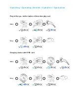
Page 6: ...or or Operating Operating Betrieb Opération Operazione Charging station with RFID card Plug Charge Authorisation without charging card Start 1 2 3 4 Start 1 2 3 Stop 1 2 3 Stop 1 2 3 4 3 sec 3 sec ...

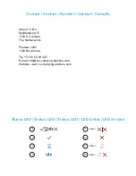
Page 7: ...tbus 1042 1300 BA Almere Tel 31 36 54 93 400 E mail info icu charging stations com Website www icu charging stations com Contact Contact Kontakt Contact Contatto Status LED Status LED Status LED LED d état LED di stato 15 16 17 18 19 20 21 22 Flicker Flicker Flicker ...

Page 8: ...Alfen ICU B V Splijtbakweg 15 Almere NL Tel 31 36 549 34 00 E mail info icu charging stations com www icu charging stations com Subject to modifications and amendments ...

Page 9: ... 9 4 2 Putting into operation 9 5 Connectivity 10 5 1 Backend Services 10 5 2 UTP Ethernet connection 10 5 3 Registering your ICU EZ account 10 Declaration of Conformity Name of manufacturer Alfen ICU B V Splijtbakweg 15 1333 HC Almere The Netherlands Declares the conformity of the product Charging stations of Type ICU Eve Following the Euopean Directives Low Voltage Directive 2014 35 EU EMC direc...

Page 10: ...es are close If the product is in the water At ambient temperatures of less than 30 C or over 40 C When the product or individual components are damaged For children or persons who can not assess the risk in handling the product In the following cases Alfen ICU B V accepts no liability for damages The warranty on products and accessories expires in the following cases Failure to follow these Insta...

Page 11: ... for cable to be connected 17 The charging station and vehicle are communicating Electric vehicle is full or charging is on hold 18 Vehicle is charging 19 External error The cable has been left too long in the charging station without starting a charging process 20 The charging station has an internal error 21 The card reader is active 22 The used card is not authorized Product Identification Labe...

Page 12: ...A 400 V Output vehicle connection Connection system 1 or 2 x type 2 connector type 2 S France only in accordance with IEC62196 2 Output Voltage 230 V or 400 V Max charging current 16 A 1 phase or 16 A 3 phase or 32 A 3 phase Max output 3 7 kW or 7 4 kW or 11 kW or 22 kW Shut down Standby all contacts Dynamic load balancing yes optional Protection integrated compo nents RCCB integrated RCCB Type B ...

Page 13: ...ICU Connect optional or other backend on request Communication with Smart Meter P1 Port Operating conditions Operating temperature 30 C to 40 C Relative humidity 5 to 95 Class of protection I Degree of protection housing IP54 IK Protection IK10 Stand By consumption C 20 W Housing Type Wall mounted housing Fixing type Plug and screw mounting or screwed to a pole optional Material cover Fiberglass r...

Page 14: ...ure that the following requirements for the installation of the ICU Eve are fulfilled The cable route from the main distribution to the ICU Eve must be secured with a miniature circuit breaker MCB with characteristic B or a screw or blade fuse gG against overvoltage and short circuit The cable route must be secured against acci dental contact 30 mA by a type A or B residual current circuit breaker...

Page 15: ...n when it is connected to the vehicle It should not be possible to drive over the cable 3 3 Mechanical installation The following tools and materials to install the ICU Eve Spirit level Impact Drill Screwdriver for an M5 cross recess hole Screwdriver for a terminal block Pencil and provided drilling template Torx M5 T25 Wire Stripper Allen key 4 x M5 x 30mm screws 4 x M5 x 30mm plugs 4 x M5 rings ...

Page 16: ...ing unit and is secured with two screws at the top and bottom 1 Place the device on its back 2 Loosen the screws on the bottom with an Allen key 3 Loosen with a Torx M5 T25 the two screws on the side of the rear housing 4 Keep the screws in a safe place they will be required later 5 Lift the front cover from the bottom upwards 6 Loosen the wiring of the LED and optional on the display 13 on the le...

Page 17: ...ating Follow the below safety instructions before putting your charger into operation 1 Make sure that the charging station is securely connected to the house supply line as specified in this manual 2 Make sure that the supply line in the house dis tribution is separately protected by an appropri ate circuit breaker B characteristic 3 Make sure that the built in charger or external upstream RCD is...

Page 18: ...station 12 on the left of the cover 4 Turn on the power of the charging station by putting the main switch to the 1 position 5 In order for your charging station to communi cate with ICU EZ through a wired UTP ethernet connection your network setting should be ad justed if these are additionally secured Below you will find the necessary information to allow access through your network IP address I...

Page 19: ...11 ENGLISH EN ...

Reviews: