background image

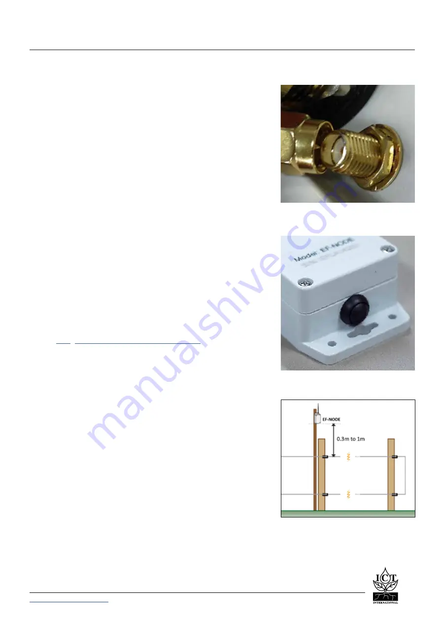
The EF-NODE Box - 

Power On/Off Button

Installation Diagram

2.1 Attaching The Antenna

Before attaching the Antenna, remove the risk of inducing an static 

electric discharge to the Node by carefully grounding the SMA (M) 

pin of the Antenna to the outer brass rim of the SMA (F) connector 

on the Node.

2.2 Device Power & Power Button

The EF-NODE runs off 3x 1.5V AA batteries – ICT International 

recommends Energizer Ultimate Lithium or similar high-end 

batteries.
To begin transmitting, press the power button at the bottom of the 

device, this button is a latching switch and we remain on until the 

button is pressed again.

2.3 Pre-Installation Device Configuration

Connect the device to the computer, following the instructions in 

Section 3 ‘Device Configuration’. 

From the computer, connect the device to the Network Server, 

such as 

TTN

 (

https://www.thethingsnetwork.org/

). Settings such as 

upload intervals, user settings and general commands can be done 

prior to installation. Commands from section 3.5 ‘Unique EF-NODE 

Commands’ will need to be configured on site to callibrate with in-

situ conditions.

2.4 Installation

The EF-NODE measures RF intensity and provides a current RF 

intensity value, a relative metric callibrated to the site, which is 

used as an indication of fence pulsing strength. 

It’s recommended that the EF-NODE should be installed between 

0.3m and 1m above the electric fence.

2. Device Operation

Carefully Grounding The Antenna

ICT  INTERNATIONAL


Enabling better global research outcomes in soil, plant & environmental monitoring

5


Summary of Contents for EF-NODE

Page 1: ...EF NODE Electric Fence Node Manual...

Page 2: ...a key app 10 3 2 3 LoRaWAN Network Joined Status lora joined 10 3 2 4 LoRaWAN Public Network Mode lora net public 11 3 2 5 LoRaWAN Adaptive Data Rate lora net adr 11 3 2 6 ADR Link Check Period linkch...

Page 3: ...etween Reports report period 18 3 5 Unique EF NODE Commands 19 3 5 1 Send Fence Strength Command fence strength 19 3 5 2 Send Battery Test battery test 19 3 5 3 Fence Low Alarm fence threshold 19 4 De...

Page 4: ...ce strength is weak it will transmit a LoRaWAN alarm The unit will also periodically transmit the minimum maximum and average strength of RF interference produced by the fence LoRaWAN low power long r...

Page 5: ...he device to the computer following the instructions in Section 3 Device Configuration From the computer connect the device to the Network Server such as TTN https www thethingsnetwork org Settings su...

Page 6: ...c Site Calibrated 2 5 Site Specific Calibration Upon installation the baseline RF intensity of an operational fence should be measured using the command as defined in 3 5 1 in this manual This status...

Page 7: ...rminal terminal emulator To gain access to configuration mode the EF NODE must be switched off for a minimum of 3 minutes then connect it to the computer with USB cable while it remains off With the U...

Page 8: ...mand Description Saves the running configuration to permanent storage 3 1 3 Reload Saved Configuration load Command Input load Compatible All Device Firmware Versions Command Description Saves the run...

Page 9: ...ons Command Description Manage the device s LoRaWAN EUIs unique identifier both device and application join dependent on LoRaWAN version Command Type Syntax Used Example Command Response Type Example...

Page 10: ...key app 00112233445566778899AABBCCDDEEFF Set lora key app key lora key app key lora eui app 1122334455667788AABBCCDDEEFFGGHH 1122334455667788AABBCCDDEEFFGGHH Parameter Type Description key String 32 c...

Page 11: ...work correctly Command Type Syntax Used Example Command Response Type Example Result of Command Get lora net public lora net public status lora net public enabled Set lora net public bool lora net pu...

Page 12: ...d Type Syntax Used Example Command Response Type Example Result of Command Get linkcheck period linkcheck period period 64 Set linkcheck period period linkcheck period 0 period linkcheck period 200 20...

Page 13: ...ons Description Enables Disables LoRaWAN confirmed messaging Command Type Syntax Used Example Command Response Type Example Result of Command Get lora tx power lora tx power power 0 Set lora tx power...

Page 14: ...d US915 Band selection is not applicable to AS923 Command Type Syntax Used Example Command Response Type Example Result of Command Get lora band lora band string lora band Band set to 1 Set lora band...

Page 15: ...evice Firmware Versions Command Description Enable Disable Activation by Personalisation Mode Parameter Type Description bool Number Indicates whether to enable or disable abp mode 0 Disable 1 Enabled...

Page 16: ...decimal string representing an 4 byte EUI Examples 0x11 0x22 0x33 0x44 11223344 Command Type Syntax Used Example Command Response Type Example Result of Command Get lora net id lora net dev addr eui 1...

Page 17: ...g Command Type Syntax Used Example Command Response Type Example Result of Command Get backoff initial backoff initial string Initial Backoff Time 60 sec Set backoff initial time backoff initial 90 st...

Page 18: ...nse Type Example Result of Command Get report period report period string Report Period 900 sec Current 12 Last 0 Next 0 Set report period period report period 600 string report period 600 Report Peri...

Page 19: ...e Firmware Versions Command Description Provides current battery voltage in millivolts The example 5225 would equate with 5 22 Volts Device operates to a lower voltage limit of 4 2volts 3 5 3 Fence Lo...

Page 20: ...4 Decoder Notes Please contact ICT International for the EF NODE decoder applicable to your order and suitable for TTN https www thethingsnetwork org...

Page 21: ...Enabling better global research outcomes in soil plant environmental monitoring www ictinternational com sales ictinternational com au Ph 61 2 6772 6770 211 Mann St Armidale NSW 2350 Australia...

Reviews: