ICT DISTRIBUTION 2 Series Instruction Manual Download Page 27

LIMITED WARRANTY

ICT Limited Warranty is only intended for the benefit of the original Purchaser of this product. This Warranty is 
not transferable or assignable without the prior written permission of ICT. ICTʼs sole obligation and liability under 
this warranty is limited to either repairing or replacing defective products at the sole discretion of ICT. When 
repairing  or  replacing  the  products,  ICT  may  use  products  or  parts  that  are  new,  equivalent  to  new  or 
re-conditioned. Parts repaired or replaced during the warranty period will be under warranty for the remainder 
of the warranty period.

The warranty period on ICT products purchased new from ICT is two years. The warranty period for a repaired 
product or part thereof is ninety (90) days or the remainder of the unexpired term of the new product warranty 
period, whichever is greater. Repair or replacement of a defective product or part does not extend the original 
warranty coverage period. 

No claim will be accepted unless written notice of the claim is received by ICT in accordance with ICTʼs Return 
Material Authorization (RMA) procedure, as soon as reasonably possible after the defect is discovered. A valid 
product serial number must be provided with the RMA claim to prove eligibility. The RMA form is available on 
the ICT website at www.ict-power.com/support/warranty-repair/. 

The Purchaser shall at their own risk and cost return the defective product to ICTʼs factory or designated repair 
center once an RMA is issued by ICT. Return of the products to the customer after repair is completed shall be 
prepaid by ICT unless otherwise mutually agreed between the parties. Products shipped to ICT which have 
incurred freight damage will not be covered by this Warranty and any repairs or replacement parts, components 
or products needed will be invoiced in the full current price amount and returned freight collect to Purchaser.  It 
is  the  Purchaserʼs  responsibility  to  check  the  product  upon  receipt  for  any  damage  during  shipping  and  to 
contact the carrier or shipper regarding such damage. Product that is returned as defective, which is determined 
to operate within published specifications will be returned to the Purchaser freight collect. 

This  Warranty  will  be  void  if  the  product  has  been  subjected  to  misuse,  neglect,  accident,  exposure  to 
environmental  conditions  not  conforming  to  the  productsʼ  limits  of  operation,  improper  installation  or 
maintenance, improper use of an electrical source, defects caused by sharp items or by impact pressure, a 
force majeure event,  has been modified or repaired by anyone other than ICT or its authorized representative, 
has been subjected to unreasonable physical, thermal or electrical stress, improper maintenance, or causes 
external  to  the  unit  including  but  not  limited  to  general  environmental  conditions  such  as  rust,  corrosive 
atmospheres,  sustained  temperatures  outside  the  specified  operating  range  of  the  equipment,  exposure  to 
power  surges  and/or  electrical  surges,  improper  grounding,  mould  or  dust,  animal  or  insect  damage,  water 
damage or immersion in liquid of any kind.

ICT does not control the installation and use of any ICT product. Accordingly, it is understood this does not 
constitute a warranty of performance or a warranty of fitness for a particular purpose.

INNOVATIVE CIRCUIT TECHNOLOGY LTD.

26921 GLOUCESTER WAY  LANGLEY, BRITISH COLUMBIA, CANADA  V4W 3Y3

T 604.856.6303   F 604.856.6365   www.ict-power.com

26

The Power of Reliability   

Summary of Contents for DISTRIBUTION 2 Series

Page 1: ...855 313 108 INSTRUCTION MANUAL The Power of Reliability ICT DISTRIBUTION SERIES 2 DC Load Distribution Panel ICT180S 12I INTELLIGENT MODEL WITH REMOTE MONITORING INNOVATIVE CIRCUIT TECHNOLOGY LTD...

Page 2: ...tatus Page 10 Device Setup Page 11 Output Setup Page 12 Network Setup Page 13 E mail Setup Page 15 Alarm Setup Page 16 User Setup Page 18 Maintenance Page 19 Mobile Web App Page 20 Text Message Alarm...

Page 3: ...nd insert fuses fully 4No internal user serviceable parts Refer all product service to an authorized ICT Ltd service facility CAUTION Risk of personal injury or damage to equipment Always observe the...

Page 4: ...el which can be connected to an external alarm circuit for monitoring alarms generated by the panel Remote monitoring is available through the integrated security protected Ethernet communications por...

Page 5: ...pect panel and accessories to make sure everything is complete and in good condition 2 For rack set up install panel on the rack using appropriate size screws and star washers on all four mounting hol...

Page 6: ...ontrol connect your network interface to the Ethernet port on the back of the panel The recommended cable for Ethernet connection is Cat5e UTP network cable 8 The Alarm Form C Contacts on the back of...

Page 7: ...s checked and no fault occurred System Over Voltage Alarm System Over Current Alarm All Activate Alarm Form C Contact is not checked No power to unit Alarm Input 1 5 Activate Alarm Form C Contact is c...

Page 8: ...or screen order Figure 3 LCD Screens 7 Holding the Output Select button for 2 seconds at any screens will return you to the main screen Holding the Output Select button for 20 seconds at any screens w...

Page 9: ...onfiguration utility Line 2 Displays the fuse status OK for good fuse and OPEN for blown or missing fuse Line 3 Displays the output voltage Voltage display will blink if the voltage exceeds the Under...

Page 10: ...ddress field of the browser If the panel is connected to a network with a DHCP server the panel will be assigned an IP address automatically To find the current IP address of the panel see the LCD Ope...

Page 11: ...rowser window STATUS This page provides information on system voltage system current fuse status current level by output contact 1 through 12 and alarm status If any alarm inputs are enabled the statu...

Page 12: ...r A valid server address must also be entered in the NTP Server field NTP Server The name or IP address of the NTP Server used for date and time synchronization such as pool ntp org Time Zone Select a...

Page 13: ...e this alarm set the value in this field to 0 Amps Activate Alarm Form C Contact If this box is checked the Alarm Form C Contacts on the panel will indicate a fault condition when the over current ala...

Page 14: ...ry DNS Server for your network Secondary DNS Specify the IP address of the Secondary DNS Server for your network WEB SERVER WARNING Changing these ports may affect your ability to access the panel The...

Page 15: ...ts through SNMP If this box is unchecked all information available from the SNMP agent will be read only SNMP Contact Information Assign contact information such as an operator name and phone number f...

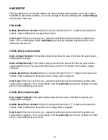
Page 16: ...s field can also be used to send a text message notification to a cell phone See the Text Message Alarm Notifications section for more information SMTP User Name If your SMTP server requires a user na...

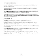
Page 17: ...e alarm will clear The value in this field must be at least 0 50V higher then the Under Voltage Threshold Activate Alarm Form C Contact If this box is checked the Alarm Form C Contacts on the panel wi...

Page 18: ...etup page must be configured correctly before e mail notifications can be sent ALARM INPUT 1 5 Alarm Name Allows you to assign a custom name to each individual alarm input Contact Type Allows you to c...

Page 19: ...eturn the password to the default setting See the Password Reset section for more information Select a User to Edit There are two user accounts with access to the panel Administrator user name admin T...

Page 20: ...TORY DEFAULT SETTINGS Pressing the Restore button will restore ALL settings to the original factory default values including the passwords If you only want to restore the network settings and password...

Page 21: ...current alarm input status fuse status and current level by output contact 1 through 12 TEXT MESSAGE ALARM NOTIFICATIONS The panel can send text message alarm notifications to a cell phone by sending...

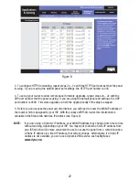
Page 22: ...ding screen In the Linksys WRT54G this is located in the Applications and Gaming tab The location of port forwarding may be different on other routers consult your router manual for instructions 2 To...

Page 23: ...eat steps 2a 2e with the HTTPS port number that the panel is using If you are using the default panel port settings the HTTPS port number is 443 4 To set up your router to allow remote panel firmware...

Page 24: ...ype the WAN IP Address of the router in the location address field of your browser followed by a colon and the HTTP port number that the panel is using e g http 209 123 10 33 8000 for IP Address 209 1...

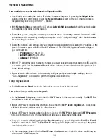
Page 25: ...he URL used to access the panel See the Password Reset section for instructions on how to reset the port number to the default setting If your network switch allows you to manually configure port spee...

Page 26: ...ltage Drop without fuse 60mV Typical Alarm Form C Contact Form C Dry Contacts 1A 60VDC Max Alarm Sensor Inputs External dry contact alarm inputs configurable for NO or NC logic Applied voltage 3 3V 0...

Page 27: ...he parties Products shipped to ICT which have incurred freight damage will not be covered by this Warranty and any repairs or replacement parts components or products needed will be invoiced in the fu...

Reviews: