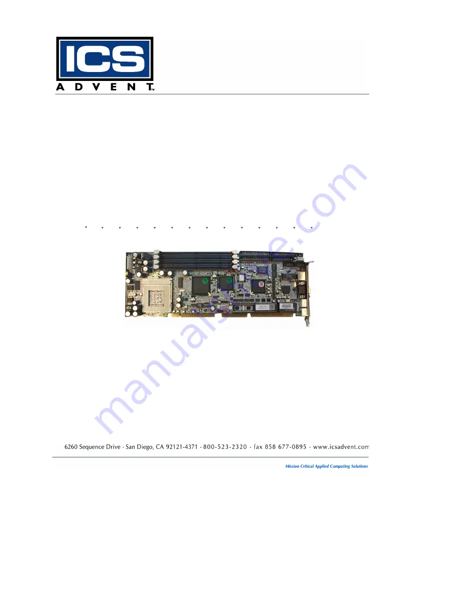
The Aviant™ BX Socket 370
Single Board Computer
User’s Guide
Manual PN: 931-0009-02-A
July 2001
Page 1: ...The Aviant BX Socket 370 Single Board Computer User s Guide Manual PN 931 0009 02 A July 2001...
Page 2: ...rising out of the application or use of the information or products described herein This document may contain or reference information and products protected by copyrights or patents and does not con...
Page 3: ...puter xv Rack Stability xvi Safety Standards xvi Regulatory Compliance Statements xvii Guarantee and Warranty Policy xviii Guarantee xviii Limited Warranty xviii Return Procedure xix Limitation of Lia...
Page 4: ...Setup 3 11 Chapter 4 BIOS Setup Information Overview 4 3 Entering Setup 4 3 Main Menu 4 5 CMOS Setup Reference Table 4 6 Standard CMOS Setup Menu 4 16 Advanced CMOS Setup Menu 4 16 Advanced Chipset Se...
Page 5: ...s Figure 1 1 Aviant BX Socket 370 1 4 Figure 2 1 Jumper Locations 2 3 Figure 2 2 Connector Locations 2 9 Figure 3 1 JP3 AT ATX Power Select Jumper Pins 3 11 Figure 3 2 JP3 AT ATX Power Select Jumper P...
Page 6: ...vi This page intentionally left blank...
Page 7: ...hen Working Inside a Computer xii Protecting Against Electrostatic Discharge xiv When Operating a Computer xv Rack Stability xvi Safety Standards xvi Regulatory Compliance Statements xvii Guarantee an...
Page 8: ...viii This page intentionally left blank...
Page 9: ...r system J Chapter 3 System Installation describes how to properly mount the CPU main memory M system s Flash Disk and the optional flat panel display interface module for safe installation It also di...
Page 10: ...under Contact Us on our Web site www icsadvent com under Technical Support Detail any errors you find We will correct the errors or problems as soon as possible and post the revised manual in our onli...
Page 11: ...any electrical component Disclaimer We have tried to identify all situations that may pose a warning or caution condition in this manual However ICS Advent does not claim to have covered all situatio...
Page 12: ...e extreme caution when installing or removing components Refer to the installation instructions in this manual for precautions and procedures If you have any questions please contact ICS Advent Post S...
Page 13: ...ecting a peripheral device from the computer J When you disconnect a cable pull on its connector or on its strain relief loop not on the cable itself Some cables have a connector with locking tabs If...
Page 14: ...unpacking a static sensitive component from its shipping carton do not remove the component s antistatic packing material until you are ready to install the component in a computer Just before unwrapp...
Page 15: ...from radiators and heat sources Do not block cooling vents or place chassis in a closed in wall unit J To help protect chassis from sudden transient increases and decreases in electrical power use a s...
Page 16: ...r vibrated resulting in possible mechanical or electrical damage to the system or injury to personnel Safety Standards The product s described in this manual has met the safety requirements of Underwr...
Page 17: ...quired to correct the interference at his or her own expense Changes or modifications not expressly approved by the party responsible for compliance could void the user s authority to operate the equi...
Page 18: ...f receipt and in an as new and resalable condition The Return Procedure must be followed to assure a prompt refund Restocking Charges Product returned after 30 days and before 60 days of the purchase...
Page 19: ...product s returned to ICS Advent for service or credit must be accompanied by a Return Material Authorization RMA Number Freight on all returned items must be prepaid by the customer who is responsib...
Page 20: ...s liability shall in no event exceed the purchase price of the product purchased hereunder The foregoing limitation of liability shall be equally applicable to any service provided by ICS Advent or i...
Page 21: ...Chapter 1 Introduction Overview 1 3 Checklist 1 5 Product Specifications 1 6 System Architecture 1 9 System Block Diagram 1 11...
Page 22: ...uter SBC The Aviant BX Socket 370 supports the PCI Industrial Computer Manufactures Group PICMG standard allowing it to work with the legacy ISA ISA PCI or multi slot PCI bus backplane The onboard 32...
Page 23: ...r connector Two IDE connectors Parallel port connector Floppy drive connector COM ports 10 100 Base T Ethernet C T 6900 display interface Socket for DiskOnChip Intel 440BX Chipset Socket 370 for Penti...
Page 24: ...le supporting two interfaces J Floppy drive cable J IDE cable J 5 pin to 5 pin keyboard cable for backplane connection J 4 pin ATX power control cable J Intel 82559 LAN driver J C T 69000 PCI VGA disp...
Page 25: ...processor J Chipset Intel 440BX chip set J Bus Interface Follows the PICMG standard 32 bit PCI and 16 bit ISA bus fully complies with PCI bus specification V2 1 J PCI IDE Interface Supports two enhanc...
Page 26: ...setting or 255 intervals from 0 5 to 254 5 minutes by software programming J Disk On Chip Feature Reserves one 32 pin socket for M systems Flash Disk up to 144MB J Onboard Video Graphics Array VGA Int...
Page 27: ...m I Board Weight 0 92 lb 0 42 kg I Printed Circuit Board PCB layout Six layers I Power Requirements 5V 6A typical 12V 140mA 12V 30mA I Operating Temperature 0 o C to 55 o C 32 o F to 131 o F I Storage...
Page 28: ...eron processor like the Intel Pentium Pro and Intel Pentium II processor features a Dynamic Execution microarchitecture and also executes MMX technology instructions for enhanced media and communicati...
Page 29: ...y jumper settings and triggered by software and a M systems Flash disk An advanced feature is used on the Aviant BX Socket 370 to support the detection of CPU temperature The CPU operation is automati...
Page 30: ...isk On Chip IDE 1 Buffer Logic 82371EB 324 BGA GTL Terminal Keyboard Mouse SUPER I O W83977ATF 128 PQFP C T 69000 VGA Panel Display ULTRA 33 Dual Channel IDE Bus Master CPU BUS CKBF Clock Buffer PCI B...
Page 31: ...Chapter 2 Hardware Configuration Settings Contents Overview 2 3 Jumpers 2 3 Connectors 2 10 Connector Pin Assignments 2 13...
Page 32: ...r testing purposes only and should not be altered To select any option insert the jumper cap Short or remove NC the jumper cap from the jumper pins according to the following instructions Here NC stan...
Page 33: ...eleron processor is calculated as 466MHz divided by 66MHz 7 0 SW1 Switch Settings for CPU Core Bus Ratio Core Bus Ratio SW 1 SW 2 SW 3 SW 4 1 5x NC NC Short NC 2 0x NC NC NC NC 2 0x Short Short Short...
Page 34: ...the CPU unless the system can handle those BIOS parameters This may damage the board and will void the warranty JP8 Disk On Chip Jumper Settings 1 2 3 4 5 6 7 8 Memory Address Window Short NC NC NC D0...
Page 35: ...H W WDT Short Disabled WDT function Short Allocate I O port 0543H 0343H for programming of H W WDT JP6 JP7 1 2 Connect WDT output to system reset 1 2 Initiated from hardware WDT by setting JP9 2 3 Co...
Page 36: ...t NC 1 second Short NC Short 2 seconds Short NC NC 4 seconds NC Short Short 8 seconds NC Short NC 16 seconds NC NC Short 32 seconds NC NC NC 64 seconds JP2 RTC CMOS Clear Setting NC Normal operation S...
Page 37: ...uration Settings JP10 and JP11 Onboard Devices VGA Ethernet Enable Disable JP10 Description JP11 Description 1 2 Normal operation 1 2 Normal operation 2 3 Disable onboard VGA 2 3 Disable onboard Ether...
Page 38: ...ard PS 2 mouse VGA display 10 100 Base T Ethernet CPU Cooling Fan Connector J14 IrDA Port J11 Floppy J6 IDE1 Primary J5 IDE2 Secondary J8 Parallel Port J9 ATX Power Control Interface J10 COM1 J21 COM2...
Page 39: ...E1 Primary interface J6 Floppy connector J8 IDE2 Secondary interface J9 Parallel port connector J10 ATX power control interface For use with chassis with ATX power supply only J11 IrDA infrared port S...
Page 40: ...se cable kit J21 COM2 serial port 2 x 5 shrouded J23 External USB interface Support two ports J24 External keyboard interface Connect to backplane J25 PS 2 keyboard connector 6 pin Mini DIN J26 VGA co...
Page 41: ...5V 2 FIRRX 1 Reset 2 Ground 3 SIRRX 4 Ground 5 IRTX 6 NC J2 External Speaker Header Pin Signal Pin Signal 1 Speaker signal 2 NC 3 Ground 4 5V J3 Keyboard Lock Header J4 IDE1 Active LED Header Pin Sig...
Page 42: ...d J9 Parallel Port Connector Pin Signal Pin Signal 1 Strobe 2 Data 0 3 Data 1 4 Data 2 5 Data 3 6 Data 4 7 Data 5 8 Data 6 9 Data 7 10 Acknowledge 11 Busy 12 Paper Empty 13 Printer Select 14 Auto Form...
Page 43: ...nsmit Data TXD 4 Data Terminal Ready DTR 5 Ground GND 6 Data Set Ready DSR 7 Request to Send RTS 8 Clear to Send CTS 9 Ring Indicator RI 10 NC J18 PS 2 Mouse Connector 6 pin Mini DIN J25 PS 2 Keyboard...
Page 44: ...a 9 7 Data 5 8 Data 10 9 Data 4 10 Data 11 11 Data 3 12 Data 12 13 Data 2 14 Data 13 15 Data 1 16 Data 14 17 Data 0 18 Data 15 19 Ground 20 NC 21 DMA REQ 22 Ground 23 IOW 24 Ground 25 IOR 26 Ground 27...
Page 45: ...6 NC 7 Ground 8 Index 9 Ground 10 Motor ENA 11 Ground 12 Drive Select B 13 Ground 14 Drive Select A 15 Ground 16 Motor ENB 17 Ground 18 Direction 19 Ground 20 Step 21 Ground 22 Write Data 23 Ground 2...
Page 46: ...gnal 1 P0 2 P1 3 P2 4 P3 5 P4 6 P5 7 P6 8 P7 9 P8 10 P9 11 P10 12 P11 13 P12 14 P13 15 P14 16 P15 17 Ground 18 P16 19 SHFCLK 20 P17 21 Ground 22 Ground 23 P18 24 P19 25 P20 26 P21 27 P22 28 P23 29 FLM...
Page 47: ...2 Ground 3 B 4 NC 5 Ground 6 Ground 7 Ground 8 Ground 9 NC 10 Ground 11 NC 12 MONID1 13 HSYNC 14 VSYNC 15 MONID2 J27 Ethernet RJ 45 Interface Connector Pin Signal Pin Signal 1 TX 2 TX 3 RX 4 Terminati...
Page 48: ...1 5V 2 NC 3 SBD0 USBP0 4 Ground 5 SBD0 USBP0 6 SBD1 USBP1 7 Ground 8 SBD1 USBP1 9 NC 10 5V J20 External PS 2 Mouse Connector J24 External PS 2 Keyboard Connector Pin Signal Pin Signal 1 Mouse clock 1...
Page 49: ...P8 Power Connector J14 CPU Cooling Fan Power Connector Pin Signal Pin Signal 1 N C 1 Ground 2 5V 2 12V 3 12V 3 Pull up 5V reserved for fan sense 4 12V 5 Ground 6 Ground J12 ATX Power Button Interface...
Page 50: ...Main Memory 3 4 Flash Disk 3 5 Installing DOC 3 5 Installing the Single Board Computer 3 6 CHIPS 69000 Graphics Controller 3 7 Display Modes Supported 3 7 Intel 82559 Fast Ethernet Controller 3 8 Onbo...
Page 51: ...ttings properly 2 Lift the CPU socket lever outwards and upwards 3 Align the processor pins with the pin holes in the socket Make sure the notched corner or dot mark pin 1 of the CPU corresponds to th...
Page 52: ...the DIMM used can be either 3 3V EDO memory with a speed less than 70ns or 3 3V Synchronized DRAM SDRAM with a speed less than 10ns If you use a Pentium III processor with a 100MHz system clock it is...
Page 53: ...hip from burning out due to incorrect installation Installing DOC Align the DOC with the pin holes on the socket Make sure that the notched corner or dot mark pin 1 of the DOC corresponds to the notch...
Page 54: ...roperly 2 Install and configure the CPU and memory module 3 Place the Aviant BX Socket 370 into the dedicated position in your system 4 Attach cables to the existing peripheral devices and secure it N...
Page 55: ...cs subsystem to support high color high resolution applications The 69000 supports a wide variety of monochrome and color Single Panel Single Drive and Dual Panel Dual Drive standard and high resoluti...
Page 56: ...will show you how to enable and or disable the onboard Intel 82559 LAN interface by putting jumpers at their proper positions Ethernet Driver Support The 82559 LAN driver is located in the Drivers dir...
Page 57: ...ED indicators to show the status of the LAN interface These messages will assist in troubleshooting LED1 top LAN speed ON indicates 100Mbps activity OFF indicates 10Mbps activity LED2 center LAN activ...
Page 58: ...difficult and complicated In addition you may also connect the WDT output to the NMI input by setting jumper JP6 to generate an NMI event The WDT comes with eight possible ranges of time intervals fr...
Page 59: ...entary power switch follow these steps 1 Select jumper pins 1 2 on JP3 AT ATX Power Select Figure 3 1 2 Connect J12 ATX Power Button Interface to the momentary power switch on the chassis 3 Route ATX...
Page 60: ...on off power switch follow these steps 1 Select jumper pins 2 3 on JP3 AT ATX Power Select 2 Make sure that J12 ATX Power Button Interface is not connected 3 Make sure that J10 ATX Power Control Conn...
Page 61: ...d CMOS Setup Menu 4 16 Advanced Chipset Setup Menu 4 19 Power Management Setup Menu 4 22 Power Management APM 4 22 PCI Plug n Play Setup 4 25 Peripheral Setup 4 28 Hardware Monitor Setup 4 31 BIOS POS...
Page 62: ...rameters need to be initially defined the diagnostic program will prompt the user to enter the SETUP program Some errors will abort the start up The Setup program is for viewing and changing the BIOS...
Page 63: ...s options Editing Keys Function Tab Move to the next field Move to the next field to the left above right or below Enter Select in the current field Increment Decrement a value Esc Close the current o...
Page 64: ...Inc All Rights Reserved Standard CMOS SETUP Advanced CMOS SETUP Advanced Chipset SETUP Power Management SETUP PCI Plug and Play SETUP Peripheral SETUP Hardware Monitor SETUP Auto Detect Hard Disks Ch...
Page 65: ...l Default Failsafe Default Other Options Quick Boot Enabled Disabled 1st Boot Device Floppy Floppy IDE 1 IDE 2 IDE 3 Floppy CD ROM ATAPI ZIP LS 120 SCSI Network 2nd Boot Device IDE 0 IDE 0 IDE 1 CD RO...
Page 66: ...System BIOS Cacheable Enabled Disabled C000 16K Shadow Cached Cached Enabled Disabled C400 16K Shadow Cached Cached Enabled Disabled C800 16K Shadow Cached Cached Enabled Disabled CC00 16K Shadow Dis...
Page 67: ...to CAS delay 3 SCLKs 3 SCLKs 2 SCLKs SDRAM RAS Precharge 3 SCLKs 3 SCLKs 2 SCLKs SDRAM CAS Latency 3 SCLKs 3 SCLKs 2 SCLKs SDRAMLeadoff Cmd Timing Auto Auto 4 SCLKs 3 SCLKs DRAMIntegrity Mode Non ECC...
Page 68: ...X4 Passive Release Enabled Enabled Disabled PIIX4 Delayed Transaction Disabled Disabled Enabled USB Function Enabled Enabled Disabled USB Keyboard Legacy Support Enabled Enabled Disabled LCD CRT Selec...
Page 69: ...ndby Suspend Hard Disk Power Down Mode Disabled Disabled Standby Suspend Standby Time out Minute Disabled Disabled 1 2 4 8 10 20 30 40 50 60 minutes Suspend Time out Minute Disabled Disabled 1 2 4 8 1...
Page 70: ...ice 3 Secondary slave IDE Ignore Ignore Monitor System Thermal Ignore Ignore Monitor Thermal Slow Clock Ratio 50 to 62 5 50 to 62 5 0 to 12 5 12 5 to 25 25 to 37 5 37 5 to 50 62 5 to 75 CPU Critical T...
Page 71: ...28 160 192 224 248 PCI VGA Palette Snoop Disabled Disabled Enabled Allocate IRQ to PCI VGA Yes Yes No PCI IDE BusMaster Disabled Disabled Enabled Offboard PCI IDE Card Auto Auto Slot1 Slot2 Slot3 Slot...
Page 72: ...DMA Channel 3 PnP PnP ISA EISA DMA Channel 5 PnP PnP ISA EISA DMA Channel 6 PnP PnP ISA EISA DMA Channel 7 PnP Pnp ISA EISA IRQ3 PCI PnP PCI PnP ISA EISA IRQ4 PCI PnP PCI PnP ISA EISA IRQ5 PCI PnP PCI...
Page 73: ...Peripheral Setup Defaults BIOS Setup Items Optimal Default Failsafe Default Other Options Onboard FDC Auto Auto Enabled Disabled Onboard Serial PortA Auto Auto 3F8h COM1 2F8h COM2 3E8h COM3 2E8h COM4...
Page 74: ...1 12 IR DMA Select N A N A 0 1 3 OnBoard Parallel Port Auto Auto Disabled 378h 278h 3BCh Parallel Port Mode ECP ECP EPP Normal Bi Dir EPP Version N A N A 1 7 1 9 Parallel Port IRQ Auto Auto 5 7 Parall...
Page 75: ...features of the system The detailed descriptions are specified as below Quick Boot Set Disabled for normal booting or select Enabled to skip minor BIOS test items to obtain quick boot response Boot U...
Page 76: ...ore running setup if you have already entered the current user password in Change User Password The system will boot denying access to setup Always Password prompt appears every boot up The system wil...
Page 77: ...aster adapter s ROM execution However this shadow function is chipset oriented and dependent on system hardware features In general C000 and C800 will be allocated for VGA BIOS and set to Cached to ge...
Page 78: ...n SDRAM RAS to CAS Delay This option controls the number of SDRAM Clocks SCLKs from a row activate command to a read or write command Normally the option will be set to 3 SCLKs SDRAM RAS Precharge Thi...
Page 79: ...for memory space requirements from ISA bus cards 8bit I O Recovery Time This option specifies the length of the delay in Sysclks inserted between consecutive 8 bit I O operations 16bit I O Recovery Ti...
Page 80: ...the Disabled setting from the foregoing USB Function option Otherwise enabling this option provides support for a USB keyboard without the auxiliary driver in a DOS environment CMOS RAM Clear Functio...
Page 81: ...turn off heavy power The Off state is really to turn off the power of the monitor Video Power Down Mode This option specifies the power conserving state that the Video Electronics Standards Associati...
Page 82: ...fies whether the BIOS will monitor activity on the display monitor for power conservation purposes If set to Monitor and the computer is in a power saving state BIOS watches for video display activity...
Page 83: ...time the STPCLK signal is asserted while in the over heat mode CPU Critical Temperature Set this option to monitor the CPU thermal trip point defined by the user If the System Thermal option in CMOS s...
Page 84: ...enable all other PnP aware adapter cards and are PnP aware Set this option to No if the operating system such as DOS OS 2 Windows 3 x does not use PnP Clear NVRAM This option is used to clear NVRAM a...
Page 85: ...board PCI IDE controller card is installed If an offboard PCI IDE controller is used the onboard IDE controller on the SBC is automatically disabled If Auto is selected BIOS automatically determines t...
Page 86: ...se options allow you to specify IRQs for use by legacy ISA adapter cards These options determine if AMI BIOS should remove an IRQ from the pool of available IRQs passed to devices that are configurabl...
Page 87: ...Port B These fields control the resource assignments of two onboard serial interfaces SIO1 and SIO2 The following list shows the options of onboard serial port A port B Auto set serial I O resources...
Page 88: ...rt mode ECP and EPP are both bi directional data transfer schemes that adhere to the IEEE 1284 specifications This parallel port mode includes four options Normal Bi Dir EPP and ECP The optimal defaul...
Page 89: ...he onboard parallel port option is set to Enabled This option sets the IRQ used by the parallel port Parallel Port DMA Channel This option is only available if the onboard parallel port is set to fixe...
Page 90: ...enever a recoverable error occurs during the POST the system BIOS will display an error message explaining the problem in detail so that the problem can be corrected During the POST the BIOS signals a...
Page 91: ...D4 Returning to real mode Executing any OEM patches and setting the stack D5 Passing control to the uncompressed code in shadow RAM at E000 0000h The INIT code is copied to segment 0 and control will...
Page 92: ...drive EE Looking for a diskette in drive A and reading first sector of the diskette EF A read error occurred while reading the floppy drive in drive A F0 Searching for the AMIBOOT ROM file in the root...
Page 93: ...ard BAT command is issued 0C The keyboard controller input buffer is free Issuing the BAT command to the keyboard controller 0E The keyboard controller BAT command result has been verified Performing...
Page 94: ...e setting video mode 28 Beginning monochrome mode and color mode settings 2A Bus initialization system static output devices will be done if present 2B Passing control to the video ROM to perform any...
Page 95: ...memory test 43 Entered protected mode Enabling interrupts for diagnostics mode 44 Interrupts enabled if the diagnostics switch is on Initializing data to check memory wraparound at 0 0 45 Data initia...
Page 96: ...ing the memory test Performing the sequential and random memory test 50 Memory testing initialization below 1MB completed Adjusting the displayed memory size for relocation and shadowing 51 The memory...
Page 97: ...suing the keyboard reset command 81 A keyboard reset error or stuck key was found Issuing the keyboard controller interface test command 82 The keyboard controller interface test completed Writing the...
Page 98: ...ng the hard disk drive controller 95 Initializing the bus option ROMs from C800 96 Initializing before passing control to the adaptor ROM at C800 97 Initialization before the C800 adaptor ROM gains co...
Page 99: ...ty and the NMI A7 NMI and parity enabled Performing any initialization required before passing control to the adaptor ROM at E000 A8 Initialization before passing control to the adaptor ROM at E000h c...
Page 100: ...1 BIOS Setup Flash BIOS Utility Utilize the AMI Flash BIOS programming utility to update the onboard BIOS for future BIOS versions Please contact ICS Advent to get this utility if necessary Note Boot...
Page 101: ...Appendix A Abbreviations...
Page 102: ...t AT Advanced Technology ATX Advanced Technology Extended BIOS Basic Input Output System bps bits per second CE European Community CFM Cubic Feet per Minute such as 47 CFM of air flow COM Component Ob...
Page 103: ...etic Interference EN European Norm EPP Enhanced Parallel Port ESD Electrostatic Discharge FDD Floppy Disk Drive FIFO First In First Out FIR Fast Infrared GTL Gunning Transceiver Logic HDD Hard Disk Dr...
Page 104: ...PCB Printed Circuit Board PCI Peripheral Component Interconnect PICMG PCI Industrial Computer Manufactures Group PIIX4 82371EB PCI ISA IDE Xcelerator PG Power Good PIO Programmed Input Output POST Pow...
Page 105: ...ment Bus SPD Serial Presence Detect SPP PC compatible Printer Port SRAM Static Random Access Memory STN Super Twisted Nematic SVGA Super Video Graphics Array TFT Thin Film Transistor UARTS Universal A...
Page 106: ...ity for AC and I O Lines EN 60950 1992 Safety of Information Technology Equipment The technical documentation required to demonstrate this product meets the requirements of the EMC Directive and the L...