background image

Manual Number: 00650-146-1

Page 8

PCI-COM485/8 Manual

Chapter 2:  Functional Description

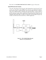
The PCI-COM485/8 Serial Interface Card was designed for effective multipoint transmission in
RS-485 (EIA485) protocol. The card is 7.83 inches long and may be installed in 5-volt PCI-bus
slots of IBM PC or compatible computers. The card features eight independent, asynchronous RS-
485 serial ports, type 16550 buffered UARTS, and, for Windows compatibility, automatic control
to transparently enable/disable the transmission drivers.

RS-485 Balanced Mode Operation

The PCI-COM485/8 supports RS-485 communications and uses differential balanced drivers for
long range and noise immunity. RS-485 operation involves switchable transceivers and the ability
to support multiple devices on a single  “party line”. The RS-485 specification defines a maximum
of 32 devices on a single line. The number of devices served on a single line can be expanded by
use of “repeaters”.

PCI-COM485/8 also has the capability to add load resistors to terminate the communications lines.
RS-485 communications requires that one transmitter supply a bias voltage to ensure a known
“zero” state when all transmitters are off. Also, receiver inputs at each end of the network should be
terminated to eliminate “ringing”. The PCI-COM485/8 supports biasing by default and supports
termination by jumpers on the card. If your application requires the transmitter to be un-biased,
please contact the factory.

Comm Port Compatibility

Type 16550 UART’s are used as the Asynchronous Communication Element (ACE).  These in-
clude a 16-byte transmit/receive buffer to protect against lost data in multitasking operating sys-
tems, while maintaining 100% compatibility with the original IBM serial port. The system assigns
the address(es).

A crystal oscillator is located on the card. This oscillator permits precise selection of baud rate up
to 115,200 or, by changing a jumper, up to 460,800 with the standard crystal oscillator.

The driver/receiver used, the SN75176B, is capable of driving extremely long communication
lines at high baud rates. It can drive up to ±60 mA on balanced lines and receive inputs as low as
200 mV differential signal superimposed on common mode noise of +12 V or -7 V.  In case of
communication conflict, the driver/receivers feature thermal shutdown.

Communication Mode

PCI-COM485/8 supports Half-Duplex communications with a 2-wire cable connection. Half-Du-
plex allows traffic to travel in both directions, but only one way at a time. RS-485 communications
commonly use the half-duplex mode since they share only a single pair of wires.

Baud Rate Ranges

The card has capability for two baud rate ranges and you can select which you wish to use on a
port-by-port basis. One range is up to 115,200 baud applications and the other is up to 460,800
baud.

Summary of Contents for PCI-COM485/8

Page 1: ...Model PCI COM485 8 Product Manual MANUAL NUMBER 00650 146 1B...

Page 2: ...ual in our online Support Library Thank you The information in this document is provided for reference only ICS Advent does not assume any liability arising from the application or use of the informat...

Page 3: ...Page iv This page intentionally left blank...

Page 4: ...ts which are not in an as new and re saleable condition are not eligible for credit return and will be returned to the customer Limited Warranty Effective April 1 1998 all products carry a 2 year limi...

Page 5: ...made by various manufacturers in performing warranty repairs and building replacement products If ICS Advent repairs or replaces a product its warranty term is not extended ICSAdvent will normally re...

Page 6: ...Cautions and Warnings are accented with triangular symbols The exclamation symbol is used in all cautions and warnings to help alert you to the important instructions The lightning flash symbol is us...

Page 7: ...Page viii This page intentionally left blank...

Page 8: ...s 5 Input Output Connections 6 Chapter 2 Functional Description 8 RS 485 Balanced Mode Operation 8 Comm Port Compatibility 8 Communication Mode 8 Baud Rate Ranges 9 Auto RTS Transceiver Control 9 Chap...

Page 9: ...f Figures Figure 2 1 PCI COM485 8 BLOCK DIAGRAM 9 Figure 3 1 PCI COM485 8 Option Selection Map 11 List of Tables Table 1 1 Pin Connections 7 Table 5 1 Baud Rate Divisor Values 14 Current Revision 1B D...

Page 10: ...propriate 2 Change the active drive to A by typing a Enter 3 Type install Enter and follow the on screen prompts The installation process will create several directories on your hard disk If you accep...

Page 11: ...DeviceIOControl handles direct to the SYS file slightly faster ACCESNT EXE Run this program on Windows NT to prepare ACCES32 DLL for use This is the install program for the SYS file itself The ACCESN...

Page 12: ...Windows 95 pro grams PCI32 This program is used to determine the base address and IRQ of installed PCI cards in Windows 95 98 and NT Run this program to both install and use NtioPCI SYS or PCIFind DLL...

Page 13: ...nter the CMOS setup program of your system and verify that the PCI plug and play option is set appropriately for your system Systems running Windows95 or any other PNP compliant Operating System shoul...

Page 14: ...uble click to run the PCINT EXE program This pro gram copies NTIOPCI SYS to the NT SYSTEM32 DRIVERS directory and dynamically loads and runs the driver Note If you previously installed an older versio...

Page 15: ...ss 0xFC00 with an interrupt of 05 the values in the Registry are Serial2 subkey Serial6 subkey PortAddress REG_DWORD 0xFC00 PortAddress REG_DWORD 0xFC20 Interrupt REG_WORD 5 Interrupt REG_DWORD 5 DosD...

Page 16: ...P m h O 0 0 1 u r h t D N G 9 2 n i P m h O 0 0 1 u r h t D N G 5 n i P n i A 0 3 n i P n i E 6 n i P n i A 1 3 n i P n i E 7 n i P d n u o r G D N G 2 3 n i P d n u o r G D N G 8 n i P t u o B 3 3 n...

Page 17: ...by default and supports termination by jumpers on the card If your application requires the transmitter to be un biased please contact the factory Comm Port Compatibility Type 16550 UART s are used a...

Page 18: ...is ready to be transmitted The driver remains en abled for one additional character s transmission time after data transfer is complete and then is disabled The receiver is also normally enabled then...

Page 19: ...it receive input output for RS 485 operation Simplified Termination Schematic In RS 485 operations where there are multiple terminals only the RS 485 ports at each end of the network should have termi...

Page 20: ...beled CLK X1 and CLK X4 provide means to select baud rates in either of two ranges When in the X1 position the baud rate range is up to 115 200 baud When in the CLK X4 position the baud rate range is...

Page 21: ...rd s base address You can only determine what the system has assigned To determine the base address that has been as signed run the provided PCIFind EXE or PCINT utility program Alternatively some ope...

Page 22: ...d 2 RS 485 Programming Programming the UART for RS 485 communication can be divided into three distinct sections initialization reception and transmission Initialization deals with option setup on the...

Page 23: ...stances for differentially driven data cables RS422 or RS 485 are for typical conditions RS 232 communication lines have a maximum length of 50 feet regardless of speed In C the code to set the chip t...

Page 24: ...op and uses a value of 13 ASCII Carriage Return as an end of transmis sion marker do while inportb BASEADDR 5 1 Wait until data ready data i inportb BASEADDR while data i 13 Reads the line until null...

Page 25: ...r at Base Address 5 That bit is the transmitter holding register empty flag If it is high the transmitter has sent the data The process of checking the bit until it goes high followed by a write is re...

Page 26: ...3 1995RadiatedRFFieldImmunity EN61000 4 4 1995EFTImmunityforACandI OLines EN 60950 1992 Safety of InformationTechnology Equipment Thetechnicaldocumentationrequiredtodemonstratethisproductmeetstherequi...

Reviews: