


I-8120W Quick Start User Guide (Version 1.2, Apr/22/2015) -----
2
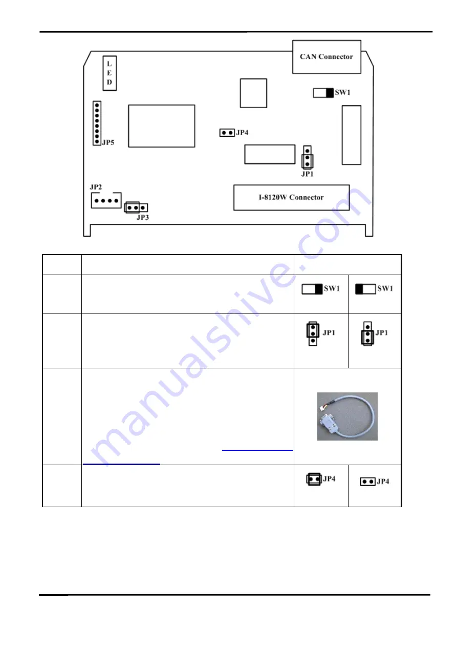
Jumper
Description
Status
SW1 120
Ω
terminator resistance of CAN port.
Enable
Disable
JP1
Lock mode for resisting the noise or disturbances.
In this case, updating firmware is not allowed.
Unlock mode for updating the firmware of I-8120W.
Lock
Unlock
JP2
Debug port for user-defined firmware. The I-8120W
prints the debug messages or system information
from this port. Connect this port to PC COM port.
Use 7188xw.exe to show the messages. The baud
rate is 115200 bps. You can find the 7188xw.exe in
the CD. The path is
CAN/SlotModule/
I_8120W/Tools/PC
JP4
Reset mode for forcing the I-8120W into download
mode. Wiring this jumper until Tx/Rx LED and Err
LED are always ON. Then, remove the wire.
Reset
Normal
3. How to Start
Step1: Set the SW1 of the I-8120W to the proper position. Generally, the both end of
CAN bus (line topology) needs 2 terminator resistance. Each of them is 120
Ω
.
Step2: Unlock the JP1. Generally, unlock the JP1 during developing the application.


