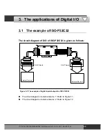
The circuit diagram of external device 2 is given as follows:
DN-37 I/O CONNECTOR BLOCK
CE
COM
Power Supply
+5.00 V
POWER
On
OFF
ICP DAS
Super 2
Vlotage Output
1
19
20
37
R33
R34
R35
R36
R37
R38
R39
R40
R41
R42
R43
R44
R45
R46
R47
R48
LED 33
LED 34
LED 35
LED 36
LED 37
LED 38
LED 39
LED 40
LED 41
LED 42
LED 43
LED 44
LED 45
LED 46
LED 47
LED 48
R49
R50
R51
R52
R53
R54
R55
R56
LED 49
LED 50
LED 51
LED 52
LED 53
LED 54
LED 55
LED 56
LED 57
LED 58
LED 59
LED 60
LED 61
LED 62
LED 63
LED 64
R57
R58
R59
R60
R61
R62
R63
R64
+
From the CON2 of ISO-C64
Figure 3-11: The circuit diagram of external device 2 for the digital outputs of ISO-C64
The resistor of R33~R64 are 330 Ohm.
The LED 33~LED 64 are light emitting diode.
The pin-1/20 are the GND signal of DO_32~DO_47 / DO_48~DO_63.
The pin-18/37 are the v) signal of DO_32~DO_47 /
DO_32~DO_63 (Input 5 V
DC
~24 V
DC
).
ISO
-P32C32/P32S32W/P64/C64 User Manual (Ver.1.9, Oct. 2011, IMH-000-19)
48

