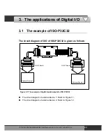
The circuit diagram of external device 2 is given as follows:
DN-37 I/O CONNECTOR BLOCK
CE
1
19
20
37
ON
ON
33
34
35
36
42
43
44
45
46
47
48
41
39
40
38
37
ON
ON
49
50
51
52
58
59
60
61
62
63
64
57
55
56
54
53
From the CON2 of ISO-P64
Figure 3-8: The circuit diagram of external device 2 for the digital inputs of ISO-P64
The D/I of CON2 of ISO-P64 select internal power.
ISO
-P32C32/P32S32W/P64/C64 User Manual (Ver.1.9, Oct. 2011, IMH-000-19)
45

