background image

428 01 9700 03

11

Crankcase Heater

The crankcase heater prevents refrigerant migration and

compressor oil dilution during shutdown when compressor

is not operating. If the crankcase heater is de

energized for

more than 6 hours, both compressor service valves must be

closed.
The crankcase heater is powered by the high

voltage

power of the unit. It is connected across the line side of the

contactor and is thermostatically controlled.

!

WARNING

PERSONAL INJURY HAZARD

Failure to follow this warning could result in

personal injury or death.
Use extreme caution when troubleshooting this

device as line voltage is continually present.

To troubleshoot:

1. Apply voltmeter across crankcase heater leads to see

if heater voltage is on. Do not touch heater. Carefully

feel area around crankcase heater; if warm,

crankcase heater is functioning.

2. With power off and heater leads disconnected, check

across leads with ohmmeter. Do not look for a specific

resistance reading. Check for resistance or an open

circuit, and change heater if an open circuit is

detected.

Service Valves

The service valves in the outdoor unit come from the factory

frontseated. This means the refrigerant charge is isolated

from the line

set connection ports. To prevent damage to

the valve, use a wet cloth or other accepted heat sink

material on the valve before brazing.
The service valve cannot be field repaired, therefore, only a

complete valve or valve stem seal and service port caps are

available for replacement.

Defrost Controls

The control, which consists of defrost control board and

defrost thermostat, interrupts the normal system heating

operation to defrost the outdoor coil, if the coil saturated

suction temperature indicates freezing temperatures.

Defrost control board can be field set to check need for

defrost every 30, 50, or 90 minutes of operating time, by

connecting the jumper (labeled W1, on the circuit board) to

the spade terminal for the defrost time desired. The board is

factory set for 90 minutes. The defrost period is field

selectable, depending upon geographic areas and defrost

demands. Control board has additional feature that allows

unit to restart in defrost cycle if room thermostat is satisfied

during defrost. Defrost control simultaneously tops outdoor

fan, energizes reversing valve solenoid to return system to

cooling cycle (outdoor unit as condenser, indoor unit as

evaporator), and activates accessory electric heater.
The defrost timer limits defrosting period to 10 minutes.

Normally, the frost is removed and the defrost thermostat

contacts open to terminate defrosting before 10 minutes

have elapsed. When defrosting is terminated, the

outdoor

fan motor is energized, and reversing valve

solenoid is de

energized, returning unit to heating cycle.

Reversing Valve

In heat pumps, changeover between heating and cooling

modes is accomplished with a valve that reverses flow of

refrigerant in the system. The reversing valve solenoid can

be checked with the power off using an ohmmeter. Check

for continuity and shorting to ground. With control circuit (24

v) power on, check for correct voltage at solenoid coil, and

for burned or overheated solenoid.
With unit operating, other items can be checked, such as

frost or condensate on refrigerant lines.
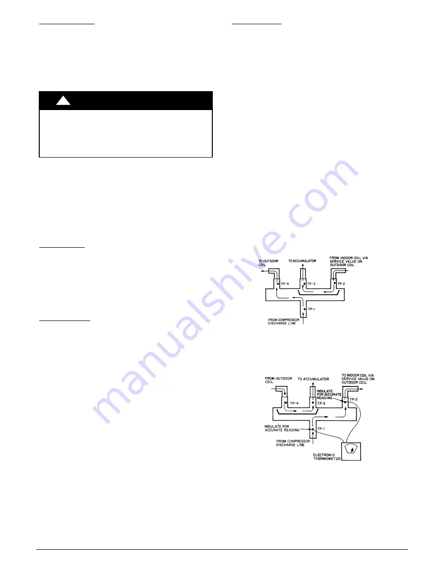
Using a remote measuring device, check inlet and outlet line

temperatures. Do not touch lines. If reversing valve is

operating normally, inlet and outlet temperatures on

appropriate lines should be similar. Any temperature

difference would be due to heat loss or gain across valve

body. Temperatures are best checked with a remote reading

electronic

type thermometer with multiple probes.

Figure 11 and Figure 12 show test points on reversing valve

for recording temperatures. Insulate points for more

accurate reading. If valve is defective:

1. Shut off all power to unit.
2. Remove all charge from system.
3. Remove valve using a tubing cutter.
4. Install new valve (wrap valve with a wet rag to prevent

overheating while brazing).

5. After valve is brazed in, check for leaks.
6. Evacuate and charge system. Operate system in both

modes several times to be sure valve functions

properly.

LEGEND

TP — 

Test Point

A07433

Figure 11

 - 

Reversing Valve

(Cooling Mode or Defrost Mode, Solenoid Energized)

LEGEND

TP — 

Test Point

A07434

Figure 12

 - 

Reversing Valve

(Heating Mode, Solenoid De

energized)

Summary of Contents for HC4H3

Page 1: ...s Use quenching cloth for brazing operations Have fire extinguisher available Read these instructions thoroughly and follow all warnings or cautions included in literature and attached to the unit Consult local building codes and National Electrical Code NEC for special requirements Recognize safety information This is the safety alert symbol When you see this symbol on the unit and in instruction...

Page 2: ...ints See Figure 3 for center of gravity Matching the Heat Pump to an Indoor Unit The HC4H3 ducted heat pump units can be matched to corresponding indoor units The HC4H3 unit can be matched with underceiling and residential fan coils and evaporator coils Refer to separate indoor unit literature for more information Expansion Device Cooling Mode A hard shutoff thermostatic expansion valve TXV is req...

Page 3: ...30 1 60 208 230 3 60 460 3 60 1 1 2 FIELD CONTROL SUPPLY WIRE ENTRY 7 8 HOLE W GROMMET 1 REQUIRED CLEARANCES WITH COIL FACING WALL ALLOW 6 MIN CLEARANCE ON COIL SIDE AND COIL END AND 36 MIN CLEARANCE ON COMPRESSOR END AND FAN SIDE WITH FAN FACING WALL ALLOW 8 MIN CLEARANCE ON FAN SIDE AND COIL END AND 36 MIN CLEARANCE ON COMPRESSOR END AND COIL SIDE WITH MULTI UNIT APPLICATION ARRANGE UNITS SO DIS...

Page 4: ...3 774 7 498 5 893 8 1017 6 368 3 215 9 479 4 22 2 87 3 165 1 139 0 150 4 1282 7 X 520 7 X 1173 1 UNIT SIZE DIMENSIONS 208 230 1 60 230 1 60 208 230 3 60 460 3 60 FIELD CONTROL SUPPLY WIRE ENTRY 22 22 HOLE W GROMMET FIELD POWER SUPPLY CONN HOLE SIZES PROVIDED 22 22 12 70 TRADE 30 16 19 05 TRADE 34 92 25 40 TRADE MEASUREMENT METR X YES O NO 1 REQUIRED CLEARANCES WITH COIL FACING WALL ALLOW 152 4 MIN...

Page 5: ... 2 3 3 3 FPI 20 20 20 20 20 20 HIGH PRESSURE SWITCH Cut In psig Cutout psig 420 25 650 10 420 25 650 10 420 25 650 10 420 25 650 10 420 25 650 10 420 25 650 10 LOW PRESSURE SWITCH Low Cutout psig Low Cut in psig 20 5 45 25 20 5 45 25 20 5 45 25 20 5 45 25 20 5 45 25 20 5 45 25 REFRIGERANT LINES Connection Type Sweat Liquid Line in OD 3 8 Vapor Line in OD 5 8 3 4 7 8 7 8 Max Length ft m 200 60 96 M...

Page 6: ... line sizes Do not use less than 10 ft 3 05 m of interconnecting tubing CAUTION UNIT DAMAGE HAZARD Failure to follow this caution may result in equipment damage or improper operation If any section of pipe is buried there must be a 6 in 152 4 mm vertical rise to the valve connections on the outdoor unit If more than the recommended length is buried refrigerant may migrate to cooler buried section ...

Page 7: ...HOCK HAZARD Failure to follow this warning could result in personal injury or death Before performing service or maintenance be sure indoor unit main power switch is turned OFF and indoor blower has stopped Power Wiring Unit is factory wired for voltage shown on nameplate Provide adequate fused disconnect switch within sight from unit readily accessible but out of reach of children Provision for l...

Page 8: ...sor control G energizes fan relay at outdoor unit and outdoor fan motor runs 4 24 v from microprocessor control Y energizes the contactor coil and the compressor will run 5 Demand defrost is controlled by the indoor unit microprocessor control 6 The indoor unit microprocessor control continuously monitors both outdoor coil temperature and outdoor ambient temperature determining the optimum defrost...

Page 9: ...nd requires external power source Copper wire must be used from service disconnect to unit 2 All motors compressors contain internal overload protection 3 In compliance with NEC U S A Standard requirements for multimotor and combination load equipment refer to NEC Articles 430 and 440 the overcurrent protective device for the unit shall be fuse 4 Motor RLA values are established in accordance with...

Page 10: ...re equalization Internal Current and Temperature Sensitive Overload The control resets automatically when internal compressor motor temperature drops to a safe level overloads may require up to 45 minutes to reset When an internal overload is suspected of being open check by using an ohmmeter or continuity tester Pumpdown Procedure The system may be pumped down in order to make repairs on the low ...

Page 11: ...reas and defrost demands Control board has additional feature that allows unit to restart in defrost cycle if room thermostat is satisfied during defrost Defrost control simultaneously tops outdoor fan energizes reversing valve solenoid to return system to cooling cycle outdoor unit as condenser indoor unit as evaporator and activates accessory electric heater The defrost timer limits defrosting p...

Page 12: ...ant R 410A refrigerant cylinders are rose colored Recovery cylinder service pressure rating must be 400 psig DOT Department of Transportation 4BA400 or DOT BW400 R 410A systems should be charged with liquid refrigerant Use a commercial type metering device in the manifold hose when charging into suction line with compressor operating Manifold sets should be 700 psig high side and 180 psig low side...

Page 13: ...47 9 64 39 58 7 3 13 72 160 56 2 13 44 262 86 9 30 50 364 110 0 43 33 466 128 7 53 72 596 148 4 64 67 60 8 6 13 00 162 57 0 13 89 264 87 4 30 78 366 110 4 43 56 468 129 0 53 89 600 149 0 65 00 62 10 0 12 22 164 57 7 14 28 266 87 9 31 06 368 110 8 43 78 470 129 3 54 06 604 149 5 65 28 64 11 3 11 50 166 58 4 14 67 268 88 4 31 33 370 111 2 44 00 472 129 7 54 28 608 150 1 65 61 66 12 6 10 78 168 59 0 ...

Page 14: ...ce of 3 F 1 67 C Table 4 Subcooling Charging Table LIQUID PRES SURE AT SERVICE VALVE REQUIRED LIQUID LINE TEMPERATURE Required Subcooling Temperature _F 5C 8 4 4 10 5 5 12 6 6 14 7 7 16 8 8 18 9 9 psig _F 5C _F 5C _F 5C _F 5C _F 5C _F 5C 189 58 32 56 31 54 30 52 29 50 28 48 27 195 60 33 58 32 56 31 54 30 52 29 50 28 202 62 34 60 33 58 32 56 31 54 30 52 29 208 64 36 62 34 60 33 58 32 56 31 54 30 21...

Page 15: ...ut with compressor air Note that the blow thru design causes dirt and debris to build up on the inside of the coils Clean coil annually or as required by location and outdoor air conditions Inspect coil monthly and clean as required Fins are not continuous through coil sections Dirt and debris may pass through first section become trapped between the row of fins and restrict condenser airflow Use ...

Page 16: ...ING LEGEND NOTE For systems with indoor units equipped with microprocessor control see separate controls service and troubleshooting manual NC Normally Closed ODT Outdoor Thermostat A07435 Figure 13 Troubleshooting the Cooling Cycle ...

Page 17: ...428 01 9700 03 17 TROUBLESHOOTING CONT A07436 Figure 14 Troubleshooting the Heating Cycle International Comfort Products LLC Lewisburg TN 37091 USA ...

Reviews: