background image

PIO-D96 Series Card 

96-channel DIO Board


User Manual,  Ver.  2.3, Jun. 2018,  PMH-008-23  Page:  32 


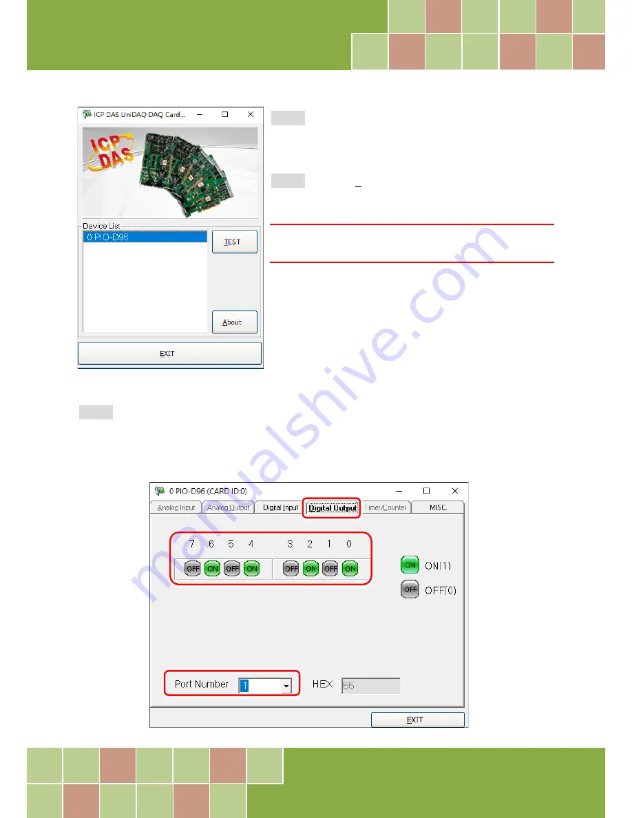
Step 2: 

Confirm that your board has been successfully 

installed in the Host system. 

Note that the device number 

starts from 0

.


Step 3: 

Click the

 “TEST”

 button to start the test. 


Note: 
The PEX-D96S, PIO-D96SU and PIO-D96U software is fully 
compatible with the PIO-D96 series software.


Step 4: 

Check the results of the 

Digital Input and Digital Output

 functions test. 

1. Click the 

“Digital Output”

 tab. 

2. Select 

“Port 1”

 from the 

“Port Number”

 drop-down menu. 

3. Check the checkboxes for 

channels


0, 2, 4 and 6


Summary of Contents for PIO-D96

Page 1: ...t to change this manual at any time without notice The information furnished by ICP DAS is believed to be accurate and reliable However no responsibility is assumed by ICP DAS for its use nor for any...

Page 2: ...I DO ARCHITECTURE 14 2 7 INTERRUPT OPERATION 15 3 HARDWARE INSTALLATION 16 4 SOFTWARE INSTALLATION 20 4 1 OBTAINING INSTALLING THE DRIVER INSTALLER PACKAGE 20 4 2 PNP DRIVER INSTALLATION 23 4 3 VERIFY...

Page 3: ...3 7 I O Selection Control Register 44 6 3 8 Card ID Register 45 6 3 9 Read Write 8 bit Data Register 45 7 DEMO PROGRAMS 46 7 1 DEMO PROGRAM FOR WINDOWS 46 7 2 DEMO PROGRAM FOR DOS 48 APPENDIX DAUGHTE...

Page 4: ...llowing items One PIO D96 Series card as follows One printed Quick Start Guide One Software Utility CD Note If any of these items is missing or damaged contact the dealer from whom you purchased the p...

Page 5: ...in the computer The PIO D96U D96SU and PEX D96S cards include an onboard Card ID switch that enables the board to be recognized via software if two or more boards are installed in the same computer T...

Page 6: ...ports 4 Interrupt source P2C0 P5C0 P8C0 P11C0 Card ID function for PIO D96U D96SU and PEX D96S Pull high low jumpers for DI channels for PIO D96U D96SU and PEX D96S PIO D96 D96U one DB37 connector and...

Page 7: ...Capability Sink 6 mA 0 33 V Source 6 mA 4 77 V Sink 64mA 0 8 V Source 32 mA 2 0 V Response Speed 500 kHz 1 MHz General Bus Type PCI Express x 1 3 3 V 5 V Universal PCI 32 bit 33 MHz 5 V PCI 32 bit 33...

Page 8: ...3 Jun 2018 PMH 008 23 Page 7 2 Hardware Configuration 2 1 Board Layout PIO D96 PIO D96U Note The JPx default settings JP2 3 4 5 6 7 9 10 11 12 13 1 2 short Pull Low refer to Section 2 2 I O Port Loca...

Page 9: ...rd User Manual Ver 2 3 Jun 2018 PMH 008 23 Page 8 PIO D96SU PEX D96S Note The JPx default settings JP2 3 4 5 6 7 9 10 11 12 13 1 2 short Pull Low refer to Section 2 2 I O Port Location for more detail...

Page 10: ...96SU PEX D96S CON1 PA0 PA7 Port0 pull high low by JP2 PB0 PB7 Port1 pull high low by JP3 PC0 PC7 Port2 pull high low by JP4 PA10 PA17 Port3 pull high low by JP5 PB10 PB17 Port4 pull high low by JP6 PC...

Page 11: ...e computer The default Card ID is 0x0 For detailed information about the SW1 Card ID settings refer to Table 2 4 Default Settings Table 2 1 Default Settings OFF 1 ON 0 Card ID Hex 1 ID0 2 ID1 3 ID2 4...

Page 12: ...IO Board User Manual Ver 2 3 Jun 2018 PMH 008 23 Page 11 2 4 Pin Assignments 2 4 1 PIO D96 and PIO D96U CON1 37 pin D type female connector for Port0 Port1 Port2 CN1 CN2 CN3 50 pin flat cable connecto...

Page 13: ...PIO D96 Series Card 96 channel DIO Board User Manual Ver 2 3 Jun 2018 PMH 008 23 Page 12 2 4 2 PIO D96SU and PEX D96S CON1 100 pin SCSI II connector for Port0 to Port11 Figure 2 2...

Page 14: ...efer to Section 2 6 DI DO Architecture The user has to perform some initialization before using these Digital I O ports The recommended steps are given below Step 1 Find the address mapping for PIO PI...

Page 15: ...T is in the High state all DI DO operation is enabled If DI DO is configured as a DI port DI external input signal If DI DO is configured as a DO port DI read back DO If the DI DO is configured as a D...

Page 16: ...s for a single interrupt source and DEMO5 C is the demo program for four interrupt sources in the DOS operating system If only one interrupt signal source is used the interrupt service routine does no...

Page 17: ...e driver first helps reduce the time required for installation and restarting the computer To install your PIO D96 series card follow the procedure described below Step 1 Install the driver for your b...

Page 18: ...Board User Manual Ver 2 3 Jun 2018 PMH 008 23 Page 17 Step 3 Shut down and switch off the power to the computer and then disconnect the power supply Step 4 Remove the cover from the computer Step 5 Se...

Page 19: ...Page 18 Step 6 Unscrew and remove the PCI slot cover from the computer case Step 7 Remove the connector cover from your board Step 8 Carefully insert your board into the PCI PCI Express slot by gentl...

Page 20: ...place using the retaining screw that was removed in Step 6 Step 10 Replace the covers on the computer Step 11 Re attach any cables insert the power cord and then switch on the power to the computer O...

Page 21: ...n CD ROM or can be obtained from the ICP DAS FTP web site Install the appropriate driver for your operating system The location and website addresses for the installation package are indicated below U...

Page 22: ...5 On the Select Components screen verify that the DAQ board is in the list of device and then click the Next button to continue Step 6 On the Select Additional Tasks screen click the Next button to c...

Page 23: ...p software Step 1 Double click the PIO DIO Series Classic Driver to setup it Step 2 When the Setup Wizard screen is displayed click the Next button Step 3 Select the folder where the drivers are to in...

Page 24: ...r For detailed information about the hardware installation of PIO D96 series board refer to Chapter 3 Hardware Installation Step 2 Power on the computer and complete the Plug and Play installation Not...

Page 25: ...PIO D96 Series Card 96 channel DIO Board User Manual Ver 2 3 Jun 2018 PMH 008 23 Page 24 Step 4 Click the Finish button Step 5 Windows pops up Found New Hardware dialog box again...

Page 26: ...The following is a description of how access the Device Manager in each of the major versions of Windows Refer to the appropriate description for the specific operating system to verify the installat...

Page 27: ...Control Panel Double click the System icon to open the System Properties dialog box Step 2 Click the Hardware tab and then click the Device Manager button Windows Server 2003 Step 1 Click the Start b...

Page 28: ...istrator privileges are required for this operation If you are prompted for an administrator password or confirmation enter the password or provide confirmation by clicking the Yes button in the User...

Page 29: ...Card 96 channel DIO Board User Manual Ver 2 3 Jun 2018 PMH 008 23 Page 28 4 3 2 Check that the Installation Check that the PIO D96 series board is correctly listed in the Device Manager window as ill...

Page 30: ...led information about the hardware and driver installation refer to Chapter 3 Hardware Installation and Chapter 4 Software Installation 5 1 Self Test Wiring 5 1 1 PIO D96 D96U Before beginning the Sel...

Page 31: ...le A CA SCSI100 15 Cable Optional Website http www icpdas com products Accessories cable cable_selection htm A DN 100 Terminal Board Optional Website http www icpdas com root product solutions pc_base...

Page 32: ...c driver refer to Quick Start Guide of the PIO D96 series http ftp icpdas com pub cd iocard pci napdos pci pio dio manual quickstart classic to execute the self test Step 1 Double click the UniDAQ Uti...

Page 33: ...vice number starts from 0 Step 3 Click the TEST button to start the test Note The PEX D96S PIO D96SU and PIO D96U software is fully compatible with the PIO D96 series software Step 4 Check the results...

Page 34: ...l DIO Board User Manual Ver 2 3 Jun 2018 PMH 008 23 Page 33 4 Click the Digital Input tab 5 Select Port 0 from the Port Number drop down menu 6 The DI indicators will turn red when the corresponding D...

Page 35: ...des four fixed ID numbers that are used to identify the board and are indicated below Table 6 1 PIO D96 Rev 1 0 3 0 PIO D96 Rev 4 0 or above Vendor ID 0xE159 0xE159 Device ID 0x0002 0x0001 Sub Vendor...

Page 36: ...information The important driver information is given as follows Allocated resource information wBase BASE address mapping in this PC wIrq Allocated IRQ channel number of this board in this PC PIO PI...

Page 37: ...o use another PCI slot and try again The user can execute the PIO_PISO EXE to get the following information List all PIO PISO cards installed in this PC List all resources allocated to every PIO PISO...

Page 38: ...rq WORD wBase2 wIrq2 int main int i j j1 j2 j3 j4 k jj dd j11 j22 j33 j44 WORD wBoards wRetVal WORD wSubVendor wSubDevice wSubAux wSlotBus wSlotDevice char c float ok err clrscr wRetVal PIO_DriverInit...

Page 39: ...to identify which card is card_0 is to use wSlotBus and wSlotDevice in the following manner Step 1 Remove all PIO D96 series boards from the PC Step 2 Install one PIO D96 series onto the PC s PCI_slo...

Page 40: ...to identify the specified PIO PISO card by following steps Step1 Using the wSlotBus and wSlotDevice information from Table 6 4 Step2 Enter the board number into PIO_GetConfigAddressSpace function to...

Page 41: ...er Same wBase 3 Aux data register Same wBase 5 INT mask control register Same wBase 7 Aux pin status register Same wBase 0x2a INT polarity control register Same wBase 0xc0 Read Port0 Write Port0 wBase...

Page 42: ...operations The user has to set the RESET signal to a High state before any DI O command applications are initiated For example outportb wBase 1 RESET High all DI O are enable now outportb wBase 0 RES...

Page 43: ...by this register This register is designed for feature extension Therefore do not use this register 6 3 4 INT Mask Control Register Read Write wBase 5 Bit 7 Bit 6 Bit 5 Bit 4 Bit 3 Bit 2 Bit 1 Bit 0...

Page 44: ...ite wBase 0x2A Bit 7 Bit 6 Bit 5 Bit 4 Bit 3 Bit 2 Bit 1 Bit 0 0 0 0 0 INV3 INV2 INV1 INV0 This register provides a function to control invert or non invert for the interrupt signal source A detailed...

Page 45: ...Write wBase 0xfc Bit 7 Bit 6 Bit 5 Bit 4 Bit 3 Bit 2 Bit 1 Bit 0 0 0 0 0 0 Port11 Port10 Port9 These registers provide the function for configuration digital input output port of the PIO D96 series C...

Page 46: ...xd4 0xd8 0xe0 0xe4 0xe8 0xf0 0xf4 0xf8 Bit 7 Bit 6 Bit 5 Bit 4 Bit 3 Bit 2 Bit 1 Bit 0 D7 D6 D5 D4 D3 D2 D1 D0 There are 12 8 bit I O ports in the PIO D96 series card Every I O port can be configured...

Page 47: ...ectly During the DLL driver installation process the install shields will register the correct kernel driver to the operation system and copy the DLL driver and demo programs to the correct position b...

Page 48: ...es UniDAQ LIB Linkage library for VC only VB6 for Visual Basic 6 UniDAQ BAS Declaration files VC NET2005 for VC NET2005 32 bit UniDAQ H Header files UniDAQ LIB Linkage library for VC only VC NET2005 f...

Page 49: ...del Library File MSC LIB PIO H MSC Declaration File MSC LIB MSCPIO_L LIB MSC Large Model Library File MSC LIB MSCPIO_H LIB MSC Huge Model Library File BC LIB PIO H BC Declaration File BC LIB BCPIO_L L...

Page 50: ...r board for DB 37 pins with DIN Rail Mountings The DN 50 is designed for 50 pin flat cable headers win DIN Rail mountings They are also designed for easy wire connection via pin to pin Use a 37 pin ca...

Page 51: ...n cable e g CA 3710 etc to connect DB 8125 to CON1 of the PIO D96 U A3 ADP 37 PCI and ADP 50 PCI The ADP 37 PCI and ADP 50 PCI are extender for the 50 pin header The one side of the ADP 37 PCI or the...

Page 52: ...ng You can use the DB 24P to sense DC signals from TTL levels up to 24 V or use the DB 24P to sense a wide range of AC signals You can also use this board to isolate the computer from large common mod...

Page 53: ...re are 24 enunciator LEDs for each relay channel and the LED light will go on when their associated relay has been activated The control scheme is illustrated below Table A5 1 DB 24R DB24RD 50 pin Fla...

Page 54: ...onnector OPTO 22 compatible for DIO 24 series 24 enunciator LEDs for indicating the status of for each relay and the corresponding LED light will go on when their associated relay has been activated T...

Page 55: ...PIO D96 PIO D96U PIO D96SU PEX D96S Cable Daughter Boards 20 Pin Flat Cable 50 Pin Flat Cable 37 Pin D sub 100 Pin SCSI II DB 37 NO NO Yes NO DN 37 NO NO Yes NO ADP 37 PCI NO Yes Yes NO ADP 50 PCI NO...

Reviews: