background image


I-7231D CPS/DCON Quick Start User Guide (Version 1.1,Oct/2004, I-7231D)  ------ 5


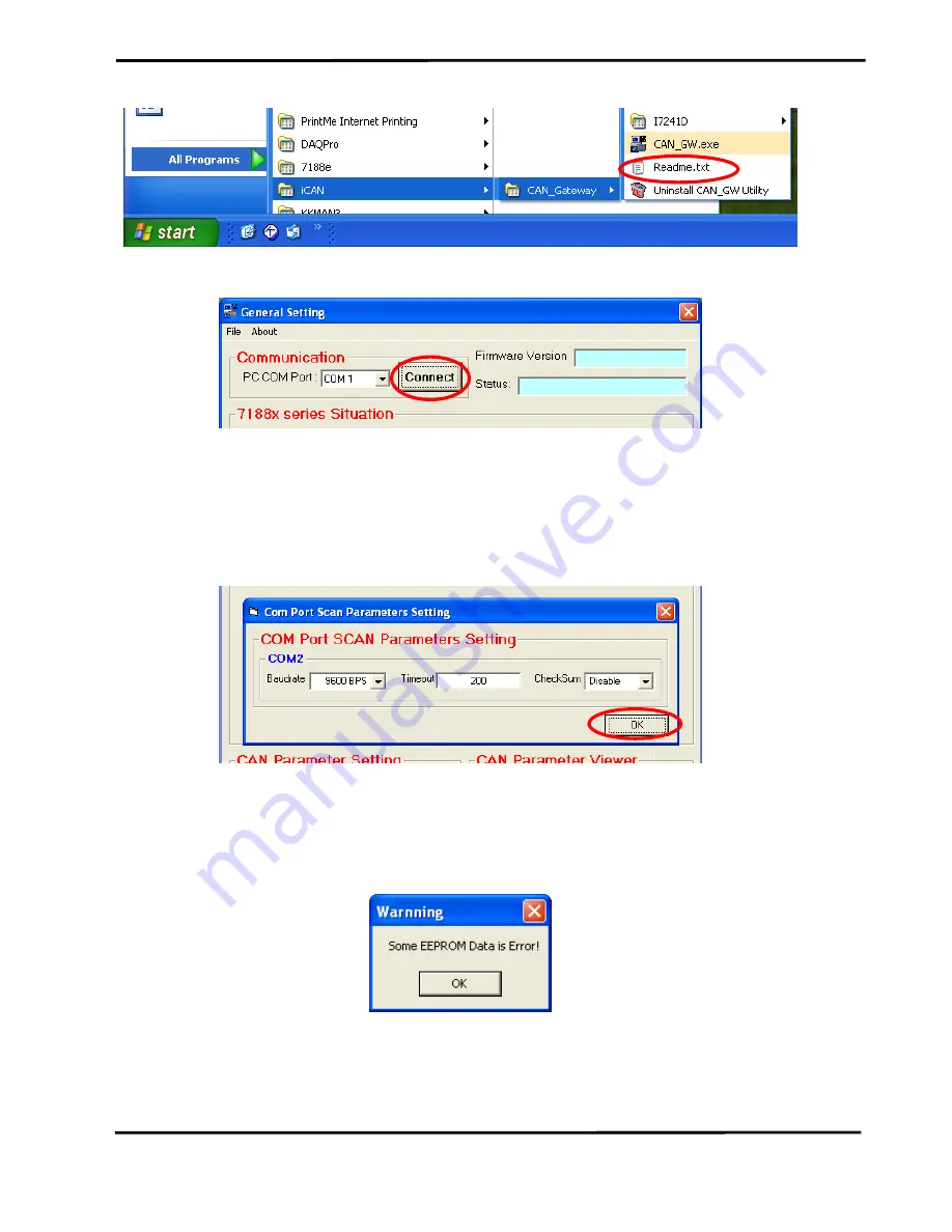
Step 4: Run the CAN Gateway Utility. 


Step 5: The first screen of the Utility would be displayed as follows. 


Step 6: Press the “Connect” button to connect the CANopen gateway. Then the “Com 

Port Scan Parameter Setting” dialog will pop up as follows. Please set the proper 

value for the RS-485 communication parameters. These parameters need to match 

with the DCON modules parameters. Then, press the “OK” button to begin the 

modules scans. 


Step 7: When the DCON modules have been scanned, the scan result will be 

compared with the parameters stored in the EEPROM of the I-7231D. If any difference 

has been detected, the warning message will pop up as follows. 


 Because the default connected modules are I-7012, I-7021, I-7053 and I-7057. If 

uses connect the I-7231D at first time with any different I/O module described above, 

the “Some EEPROM Data is Error!” warning message may pop up. In this case, the 

Summary of Contents for I-7231D

Page 1: ...cations in a quick and easy way Therefore it only provides the basic instructions For more detail information about the I 7231D please refer to the I 7231D user manual in the product CD or download it...

Page 2: ...125 K bps 9600 bps 4 250 K bps 19200 bps 5 500 K bps 38400 bps 6 800 K bps 57600 bps 7 1000 K bps 115200 bps Bypass CAN Bus Connector 7 segment LED RS 232 Port connect to PC Reserve for further use RS...

Page 3: ...s for your CANopen application Configure the RS 485 baud rate checksum module address data format and type code of the IO modules by using the DCON Utility 1 Power off the I 7231D 2 Connect these DCON...

Page 4: ...of the DCON modules If there is no RS 485 COM port on your PC the RS 232 RS 485 converter I 7520 may be needed Power on this DCON module And configure it follow the steps described in the quick start...

Page 5: ...ters These parameters need to match with the DCON modules parameters Then press the OK button to begin the modules scans Step 7 When the DCON modules have been scanned the scan result will be compared...

Page 6: ...s configuration information will be given Then users can set the necessary CAN bus communication information Afterwards click the Setting button to finish the CAN parameter setting The CAN Parameter V...

Page 7: ...tton to the next Step 10 The two fields description and create by can help user to do some notes in the EDS file If these two fields are empty the ICPDAS CANopen slave DCON master Gateway and ICPDAS w...

Page 8: ...ny CAN master interface Step 12 Power off the I 7231D and remove the wire between the Init pin and GND pin on the I 7231D Then power on the I 7231D When the I 7231D has finished the initialization the...

Reviews: