background image

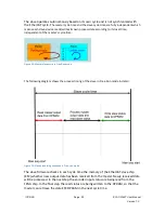
The slave operates autonomously based on its own cycle and is not synchronized with 

the EtherCAT cycle. 

The master cycle time and the slave cycle time are fully independent which

means each slave device reads/writes its own process data according to its local time, 
independent of the master’s cycle time.

Figure 13: Master-slave cycle in Free Run mode

The following diagram shows the process timing of the slave in Free Run mode in detail:

Figure 14: Slave processing sequence in Free-run mode

The slave firmware checks in each cycle time the memory of the EtherCAT slave chip 
(ESC) whether new output data has been received from the master. Newly received data 

will be processed. In the next step the encoder input status are being read from the 
FPGA chip. In the final step the read status are being written to the DPRAM, so that the 

master can retrieve the data ESC DPRAM in the next cycle time.  

ICP DAS                                                             

Page              


ECAT-2092T User Manual

Version 1.0

22

Summary of Contents for ECAT-2092T

Page 1: ...ECAT 2092T EtherCAT Two Channel Incremental Encoder Counter with Latch and Compare Function User Manual Version 1 0...

Page 2: ...The information furnished by ICP DAS is believed to be accurate and reliable However no responsibility is assumed by ICP DAS for its use nor for any infringements of patents or other rights of third...

Page 3: ...Revision Revision Date Description Author 1 18 02 2019 Initial version M K...

Page 4: ...4 6 Project Integration 27 6 1 ESI File 27 6 1 1 Import of ESI File 27 6 2 Device Setup and Configuration 27 6 2 1 Scanning of the EtherCAT Device 28 6 2 2 Encoder Counter Configuration 29 6 2 3 Ether...

Page 5: ...ard Objects 56 8 2 RxPDO Mapping Objects 57 8 3 TxPDO Mapping Objects 58 8 4 Sync Manager Objects 59 8 5 Input Data 63 8 6 Output Data 65 8 7 Configuration Data 67 8 8 Configuration Parameters Storage...

Page 6: ...tion to the encoder inputs A B and C a latch input HR for each encoder channel llows the latching and clearing of each encoder counter The ECAT 2092T supports position compare Each encoder channel is...

Page 7: ...ut pulse frequency A B Phase 4 MHz CW CCW 4 MHz Pulse Dir 4 MHz Programmable digital filter 1 250 s Input level 5V default Logic high 4 V 5 V Logic low 0 V 2 V 12 V set by jumper Logic high 5 V 12 V L...

Page 8: ...0 4 2 4 KV Contact for each channel EFT IEC 61000 4 4 Signal 1 KV Class A Power 1 KV Class A Surge IEC 61000 4 5 1 KV Class A Mechanism Installation DIN Rail Dimensions LxWxH mm 110mm x 90mm x 33mm wi...

Page 9: ...1 4 Dimensions Figure 1 Dimensions of the ECAT 2092T ICP DAS Page ECAT 2092T User Manual Version 1 0 9...

Page 10: ...oxes fasteners etc in case you need to return the product More Information Product website http www icpdas com root product solutions industrial_communication fieldbus e thercat motion ecat 2092t html...

Page 11: ...ate of the EtherCAT slave Off Device is in INIT state Flashing Device is in PREOP state Single flash Device is in SAFEOP state Outputs remain in safe state On Device is in OP state IN green Indicates...

Page 12: ...Description red Power indicator 0 1 2 3 4 5 6 7 green LED 0 A0 Channel status LED 1 B0 Channel status LED 2 C0 Channel status index input LED 3 I0 Channel status external latch input HR LED 4 A1 Chann...

Page 13: ...round GND Power supply Ground 0V from negative power contact Feeding for ECAT 2092T Vs Power supply 24 VDC from positive power contact IN EtherCAT signal input Incoming EtherCAT cable OUT EtherCAT sig...

Page 14: ...HR0 I0 Input Latch input HR0 T0 Output Compare trigger output DO0 T0 External ground for DO0 A1 Input Encoder input A1 Encoder Channel 1 A1 Input Encoder input A1 B1 Input Encoder input B1 B1 Input En...

Page 15: ...s set to support differential encoder signals as they are preferred due to their excellent noise immunity For open collector type encoder the internal resistor needs to be enabled The ECAT 2092T does...

Page 16: ...jumper of the corresponding encoder channel to the position 1 2 The housing needs to be opened in order to set the jumper For enabling the internal resistor Table 6 lists for each encoder signal inpu...

Page 17: ...A1 Differential channel Open collector channel JP10 Encoder input B1 Differential channel Open collector channel JP11 Encoder input Z1 C1 Differential channel Open collector channel JP12 Extern latch...

Page 18: ...Figure 10 Encoder counter A B index C and external latch HR input wiring 4 5 Compare Trigger Output Wiring ICP DAS Page ECAT 2092T User Manual Version 1 0 18...

Page 19: ...d connectors For connecting EtherCAT devices only Ethernet connections cables plugs that meet the requirements of at least category 5 CAT5 according to EN 50173 or ISO IEC 11801 should be used EtherCA...

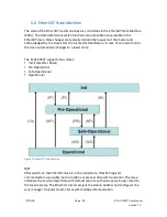
Page 20: ...lower state The ECAT 2092T supports four states Init state after Reset Pre Operational Safe Operational Operational Figure 12 EtherCAT state machine Init After switch on the EtherCAT slave is in the...

Page 21: ...automatically go from operational state to ERROR SAFEOP state Operational Op Here both the process data object PDO and service data object SDO are fully enabled Master sends cyclic output data and re...

Page 22: ...m shows the process timing of the slave in Free Run mode in detail Figure 14 Slave processing sequence in Free run mode The slave firmware checks in each cycle time the memory of the EtherCAT slave ch...

Page 23: ...the synchronization parameters Figure 15 SyncManager setting for Free Run mode 5 3 2 SM Synchron In this mode both the master and the slave are synchronized but the data exchange cycle interval is no...

Page 24: ...eously set the output e g digital output pulse output or to synchronously read inputs e g digital input encoder counter of different slaves in the EtherCAT network For system synchronization all slave...

Page 25: ...emory Every time when the master fails to sent process data within the DC cycle time the internal sync error counter is being increase by three counts This error counter is being decreased by one coun...

Page 26: ...e local memory and calculate the output value Delay Time 0x1C32 9 0x1C33 9 Delay from receiving the trigger to set the output or latch the input Cycle Time 0x1C32 2 0x1C33 2 The current cycle time for...

Page 27: ...y the XML description file ECAT 2092T xml of the ECAT 2092T device into the TwinCAT system directory and restart the TwinCAT system For TwinCat 3 1 copy the ESI file ECAT 2092T xml in the following di...

Page 28: ...earch can be started Step 1 Right click the Devices in the configuration tree to open the scan dialog Click Scan to search the ECAT 2092T device Step 2 Select OK Step 3 Select the Ethernet device Ethe...

Page 29: ...r setting etc only needs to be done once before the actual encoder counting starts These parameters have to be accessed via the CANopen over EtherCAT CoE protocol and are listed in the CoE online tab...

Page 30: ...igger NOTE The HR signal polarity can not be set for each channel individually Both channel need to be set to the same polarity Extern latch mode setting An latch signal can either latch the counter v...

Page 31: ...ccessfully sent to the slave it will be displayed in the CoE online parameter list In the figure below CW CCW counting mode has been selected for channel 0 This value needs only to be set once and the...

Page 32: ...tting The procedure for saving the configuration data is being described in chapter 7 4 6 2 3 EtherCAT Slave Process Data Assignment The user has to select the process data which has to be transferred...

Page 33: ...tch Compare trigger By selecting one of the motion mode from the list box Figure 23 all the relevant parameters are automatically assigned and mapped to the process data objects TxPDO RxPDO If require...

Page 34: ...T slave 2 For RxPDO selection click in the Sync Manager window the Outputs line and in the PDO Assignment 0x1C12 window select for each encoder channel the required RxPDO see Figure 24 If the variable...

Page 35: ...and restart TwinCAT The device is now ready to be set into Free Run or DC mode 7 Parameter Description 7 1 Configuration Parameters 7 1 1 Counting Mode The ECAT 2092T encoder counter supports three mo...

Page 36: ...serves as the direction input B high enables up count B low enables down count The ECAT 2092T counts the rising or falling edges of the A signal pulses and the B signal determines the direction of th...

Page 37: ...s going high Figure 28 Clockwise Counterclockwise counting mode In the quadrant counting mode Figure 29 the encoder counter increments when signal A leads signal B and decrements when signal B leads s...

Page 38: ...0n0 03 n represents the channel number n 0 1 By changing the signal polarity of A and or B the direction of counting may change For example By changing the signal B polarity which indicates the direct...

Page 39: ...set as follows Rising edge Active high Falling edge Active low The trigger level of the extern latch signal has to be set via CoE 0x80n0 05 n 0 1 NOTE The trigger level for extern latch can not be se...

Page 40: ...ng the input signal if and only if two consecutive samples have the same value the input is considered stable and the value is output from the filter Table 9 list the filter clocks frequencies availab...

Page 41: ...s and its pulse output trigger is directly executed by hardware and therefore without any time delay The pulse width of the output signal can be set via CoE 0x80n0 0B n 0 1 Valid value are 1 to 127 Pu...

Page 42: ...counter 0x70n0 04 from FALSE to TRUE in order to reset the encoder value to zero Reset index latch value done 0x60n0 02 Requires the 0x1An3 object to be added to the process data will be discussed in...

Page 43: ...unter value 0x60n0 11 Current encoder counter value Index latched counter value 0x60n0 12 Requires the 0x1An3 object to be added to the process data Table 13 0x1An0 Process data received from the ECAT...

Page 44: ...n set to a different value by the user Process data required for doing position compare control 0x16n0 0x16n2 0x1An0 0x1An2 n 0 1 By using TwinCAT one of the predefined PDO Assignments which contains...

Page 45: ...subtracting the Set auto increment compare value 0x70n2 08 value to from the Set first compare position value The user can always confirm the next compare position by reading the variable Get next com...

Page 46: ...extern HR latch Index latch The index latch is always enabled and can not be disabled A index signal triggers a hardware latch of the current encoder counter The ECAT 2092T allows the index latched v...

Page 47: ...ct Description Reset index latch value 0x70n0 02 When this variable turns from FALSE to TRUE then the index latch value will be cleared set to zero The status variable Reset index latch value done 0x6...

Page 48: ...0x70n1 02 input Table 20 0x1An0 Process data received from the ECAT 2092T 0x1An1 n 0 1 Parameter Object Description Extern latched counter value 0x60n1 01 Encoder value latched by the extern signal H...

Page 49: ...g external HR latch The following table Table 23 shows the procedure for resetting the index and extern latch value to zero Index Latch Resetting Extern Latch Resetting ICP DAS Page ECAT 2092T User Ma...

Page 50: ...Table 23 Resetting latch register procedure ICP DAS Page ECAT 2092T User Manual Version 1 0 50...

Page 51: ...TwinCAT System Manager for CoE parameter configuration The CoE parameters describe a wide range of features such as manufacturer ID device name process data settings and configuration parameters The r...

Page 52: ...ameters via the System Manager Figure 33 or from a TwinCAT PLC via ADS TcEtherCAT lib library If the CoE parameters of the ECAT 2092T are set online then the device does not automatically store the da...

Page 53: ...cts 0x8000 0x8010 The setting is being done by double clicking the configuration parameter and selecting an option from the shown drop list box In the following picture the signal polarity of the A si...

Page 54: ...t the Load factory default to FALSE It is always possible to return to the factory default setting by setting this value back to TRUE 5 The Save Counter F008 02 shows how often configuration data has...

Page 55: ...Step 5 Set the ECAT 2092T back into OP mode ICP DAS Page ECAT 2092T User Manual Version 1 0 55...

Page 56: ...RING RO 1 0 or greater Index 1018 Identity Index hex Name Description Data type Flags Default 1018 0 Identity UINT8 RO 0x04 1018 01 Vendor ID Vendor ID of the EtherCAT slave UINT32 RO 0x00494350 1018...

Page 57: ...1 Bit UINT32 RO 0x70n00401 16n0 05 Control__Gap5 Empty 1 Bit UINT32 RO 0x00000001 16n0 06 Control__Gap6 Empty 1 Bit UINT32 RO 0x00000001 16n0 07 Control__Gap7 Empty 2 Bit UINT32 RO 0x00000002 16n0 08...

Page 58: ...esents the channel number 0 to 1 Index 0x1An0 ENC StatusCh n TxPDO Map Index hex Name Description Data type Flags Default 1An0 0 ENC StatusCh n Encoder status UINT8 RO 0x11 1An0 01 Status__Set counter...

Page 59: ...x hex Name Description Data type Flags Default 1An1 0 Extern Latch Status Ch n Extern latch status UINT8 RO 0x01 1An1 01 Status__Extern latched counter value Extern latched encoder position 32 Bit UIN...

Page 60: ...SubIndex 002 Default assignment ENC Control Channel 1 UINT16 RW 0x1610 1C12 03 SubIndex 003 Default assignment ENC Control Channel 2 UINT16 RW 0x1620 Index 0x1C13 TxPDO assign Index hex Name Descripti...

Page 61: ...and Copy Time Minimum time between SYNC0 and SYNC1 event in ns DC mode only RO 0x00000000 1C32 08 Get Cycle Time 0 Measurement of the local cycle time is stopped 1 Measurement of the local cycle time...

Page 62: ...ported Supported synchronization modes Bit 0 1 free run is supported Bit 1 1 Synchron with SM 2 event is supported Bit 2 3 01 DC mode is supported Bit 4 5 10 Output shift with SYNC1 event only DC mode...

Page 63: ...one Assigning the counter a new value has completed Indicates whether the Set counter 70n0 04 action was successful BOOLEAN RO 60n0 02 Reset index latch value done Indicates that the index latch value...

Page 64: ...A latch event is generated every time when the trigger condition has been met INT32 RO Index 0x60n1 Extern Latch Inputs Ch n Index hex Name Description Data type Flags Default 60n1 0 Extern Latch Inpu...

Page 65: ...ter value Counter value which will be assigned to the encoder counter register see 70n0 04 INT32 RO 0 Index 0x70n1 Extern Latch Outputs Ch n Index hex Name Description Data type Flags Default 70n1 0 E...

Page 66: ...be enabled By setting this variable to FALSE the extern latch function will be disabled It is suggested to first set all the compare parameters 70n2 02 70n2 07 70n2 08 before enabling the compare tri...

Page 67: ...T0803EN01 RW 0x01 Active high 80n0 02 B signal polarity Polarity of B input signal DT0803EN01 RW 0x01 Active high 80n0 03 C signal polarity Polarity of C input signal DT0803EN01 RW 0x01 Active high 80...

Page 68: ...al EEPROM UINT8 RO 0x05 F008 01 Code Word Password for saving CoE configuration data to the EEPROM Password 0x12345678 UINT32 RW 0x00000000 F008 02 Save Counter Total number of save sequence UINT16 RO...

Page 69: ...Description Data type Flags Default the ECAT 2092T F008 05 Save error encountered Indicates whether data has been successfully written to memory BOOLEAN RO FALSE ICP DAS Page ECAT 2092T User Manual V...

Page 70: ......

Reviews: