background image

16

PREP

ARA

TION

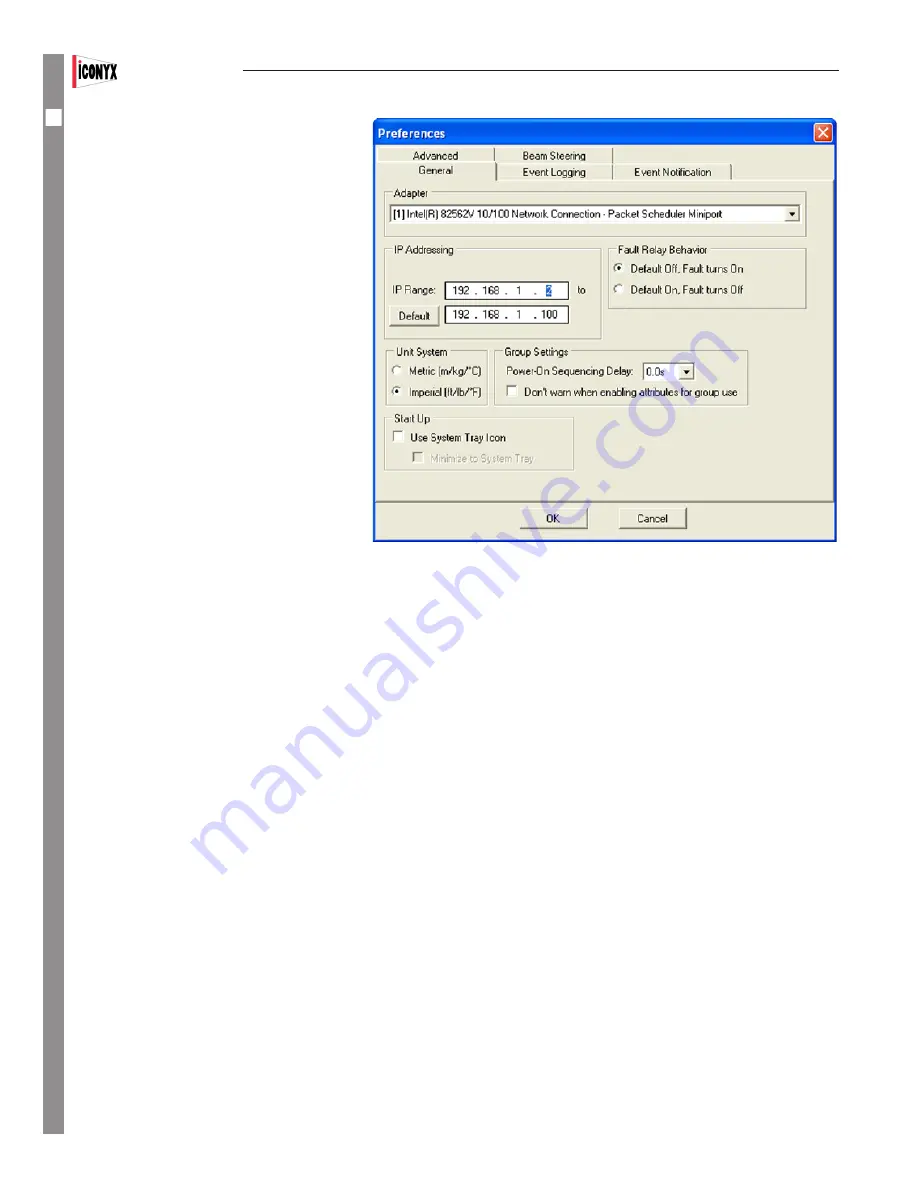
Prior to plugging a RJ-45 connector into your 

computer’s Ethernet port, you need to make sure 

that RHAON has the correct network settings.  In 

the RHAON software, go to the Options menu 

and select “Preferences”.  On the General tab, 

make sure the correct NIC is selected in the 

Adapter field.  The available selections are based 

on the listing of your network connection you 

noted earlier. Refer to page 13.

Each device on the RHAON / CobraNet net-

work must have a unique IP address in order to 

communicate over the Ethernet network.  The 

RHAON software can assign IP addresses to all 

the RHAON-Empowered loudspeakers connected 

to your network.  

Before RHAON can scan your network and 

assign IP addresses to the devices it finds, you 

need to specify a range of IP addresses to use.  

The static address assigned to the computer in 

Windows establishes the “subnet” you will be 

using.  A subnet is the first three parts (“octets”) 

of the IP address.  In the example, the subnet is 

192.168.1.  Therefore, all the IP addresses on the 

network will be in the form 192.168.1.xxx.

Type two valid IP addresses into the two fields: one for the lower limit of the range and the other for the upper limit.  Since 192.168.1.1 

is already in use by the RHAON host computer, the lower limit must be at least 192.168.1.2.  The upper limit can be set as high as 

192.168.1.255, but needs to be only high enough to accommodate all the devices on the network. Remember each device must have its 

own IP number.

Click OK and connect the computer to the RHAON/CobraNet Ethernet network, i.e., plug in the CAT5 cable. 

Note that  you do not have to create virtual loudspeakers before connecting your computer to the network. RHAON software can 

scan the local Ethernet network, identify all connected loudspeakers, assign IP addresses to them, and list them in the work-

space directory tree. Creating a virtual system before connecting to the network is an option that can in many cases save you 

time at the job site.


Saving Your Project


It’s always a good idea to save your work regularly when using any computer software. If you have not done so, RHAON will remind you 

with a prompt if you attempt to close the program without saving. 

When you are ready to save your work, selecting Save from the File pull down menu will open the familiar Windows File Save screen.   


Name your project, browse to the desired file location and Save the file. 

Note that you are saving the project file to your computer and not saving (loading) it into the loudspeakers.


IC

Users Manual

Summary of Contents for IC118S-FR

Page 1: ...C2 FR IC2 FR WR Array Modules IC212S R IC212S FR IC212S FR WR Dual 12 Subwoofers IC118S R IC118S FR IC118S FR WR 18 Subwoofers USERS MANUAL Version 1 10 4 IC2 IC Squared Digitally Steerable Loudspeaker Systems ...

Page 2: ...arly at plugs convenience receptacles and the point where they exit from the apparatus 11 Make sure the power cord remains readily accessible at all times 12 The AC Power Cord is the AC Mains disconnect 13 Only use attachments accessories specified by the manufac turer 14 Disconnect this apparatus during lightning storms or when unused for long periods of time 15 Refer all servicing to qualified s...

Page 3: ... User Configurable DSP Functions 37 Saving Changes 37 Saving To Presets 37 All Loudspeakers Group Control 39 Copy Settings Copy Presets 39 Reset 41 Supervise Mode 53 Event Logging Notification 55 General Preferences 56 Password Protection 57 Appendix I Audio Evacuation Life Safety Functions 59 Appendix II RHAON System Block Diagrams 60 IC ICR Remote Control 63 Appendix III IC2 Hardware Inputs Outp...

Page 4: ...z com support request info tech info index html IC Squared Digitally Steerable Loudspeaker Systems Your IC Squared loudspeaker system is a unique device that combines the advantages of point source design with the control and flexibility of digitally steerable line array technology Unlike traditional vertical line arrays that need to be curved to steer the sound IC Squared ar rays use digital cont...

Page 5: ...em in place with the lower cabinet s quick disconnect pins The lower cabinet s joining bars should be left in their position at the bottom of their channels unless and until they are needed to add another array module 5 Repeat the procedure with each of the four joining bars until the cabinets are isecurely fastened together Note that if a second subwoofer had been included to form base the two su...

Page 6: ...urely fastened together Note that if a second subwoofer had been included to form the base the two subwoofers would have been joined together in the same fashion Flying Arrays The procedure for assembling flying IC2 FR arrays is similar to the one used to assemble ground stacks except that the order is reversed Ground stacks are assembled from the bottom up while flown arrays are usually assembled...

Page 7: ...bolts from the top and bottom of the enclosure 5 Hold the hanging hardware in place against the side of the array inserrt and finger tighten the new M10 x 50mm bolts in place Be certain to use the liquid tread locker to ensure the bolts to not back out during operation and create a water tight seal 6 Adjust the individual enclosures placement as necessary to ensure the bolts align properly If the ...

Page 8: ...e the top module as the Master to allow you to bring the signal cables into the top of the array Set the switches in accordance with the drawing shown below In single cabinet usage and when using the All Master method of control the dip switches should always be set to the Master setting 00 Be aware that certain functions will be disabled on the Slave modules as their control has been turned over ...

Page 9: ...nt for details and assistance whenever you have a problem Access Control Note RHAON systems feature several levels of password protected access control to prevent inadvertent or unauthorized changes of the control settings Even when you connect a computer running RHAON software you may be denied access to some or all of the Connect and Control mode functions depending on how the access control sys...

Page 10: ... If you are using RHAON s CobraNet digital audio functions you will also need to connect a CobraNet source an analog to CobraNet converter to the network CONTROL You can control many DSP parameters in real time and or pre configure them in software prior to installation and make final adjustments during commissioning or setup Preset configurations are available for instant recall SUPERVISE RHAON a...

Page 11: ...Array s Sonic Beams PRESETS Control Store Presets C O N T R O L CONTROL PANEL ConfigureLoudspeaker Array EQUALIZATION 8 band parametric EQ hi and lo shelving hi pass and lo pass COMPRESSION Threshold Ratio Attack Release Soft Knee Trigger Point DELAY 0to340milliseconds 48kHz 0to170milliseconds 96kHz PRIORITY OVERRIDE Attack Release Threshold Hold Engage Disengage S U P E R V I S E OPERATOR ALERTS ...

Page 12: ...he software insert the RHAON installation disk into the computer s CD drive The installation program should start automatically During the installation you will need to select either the 32 bit or the 64 bit install RHAON 1 10 2 is downwards compatible with earlier versions of RHAON Microcontroller and DSP firmware so you do not need to uninstall a previous version of RHAON before installing progr...

Page 13: ...default 96 DPI setting to avoid viewing problems Customizing Your RHAON Workspace The grey background with RHAON watermark can easily be changed to something more useful such as a block diagram of your system or a photo of the venue To change the background go to the Options pull down menu and select Background Image Load Image Then browse to the drawing or photo you want to use IC2 ...

Page 14: ...ree format The larger section on the right displays loudspeaker icons and other specialized work areas the All Loudspeakers icon represents your loudspeak er system It functions as a group control for all the loudspeakers If you need more space on the right minimize the left hand section by clicking on the Close icon on its right edge Let s say we want to add two IC Squared IC2 loudspeakers to the...

Page 15: ...ws 8 go to Start Control Panel All Control Panel Items Network and Sharing Center Find the connection you wish to use It will likely be called Local Area Connection unless you have renamed it Also make note of the model number of the NIC you will be using The RHAON software will require you to use it later Right click on the connec tion line icon and then select Properties to open its Properties w...

Page 16: ... the other for the upper limit Since 192 168 1 1 is already in use by the RHAON host computer the lower limit must be at least 192 168 1 2 The upper limit can be set as high as 192 168 1 255 but needs to be only high enough to accommodate all the devices on the network Remember each device must have its own IP number Click OK and connect the computer to the RHAON CobraNet Ethernet network i e plug...

Page 17: ...s and not Iconyx or RHAON problems Your Iconyx IC2 loudspeakers were factory tested before they left our factory and barring shipping damage should be in perfect operating condition The RHAON Network Manager allows you to check the integrity of the Ethernet network before you actually link to the loudspeakers It is accessed from the File pull down menu and identifies network problems for you befor...

Page 18: ...e shooting hints For more detailed trouble shooting instructions please refer to page 66 The next step is to drag each loudspeaker s directory listing into the work space This will create an icon for it If you created virtual loudspeakers before scan ning the network drag each individual listing from the Network folder into the main work space and drop it on the appropriate icon When you link a ne...

Page 19: ...e first item is the icon s name The loudspeaker symbol on the right of the Status Bar is a Mute control click on it to mute or un mute the loudspeaker The green triangles on the far right represent CobraNet Transmitters Tx Each CobraNet Transmitter can transmit one channel of information from the DSP out to the CobraNet network The green Status bar reading OK at the bottom of the icon indicates th...

Page 20: ...e multiple inputs of Rhaon empowered loudspeakers to the amplifier s 2 Select and send input signals to the CobraNet network 3 Select one of the CobraNet digital audio channels if Co braNet s multi channel digital audio capability is being used The Control Properties window provides setup and control fa cilities for the loudspeaker s on board DSP It includes controls for the 1 Compressor 2 8 band ...

Page 21: ... with an actual array Loudspeakers model number or name Input signal level bar graph 0 indicates the onset of input clipping Analog inputs clip at 12 dBu without the 10 dB input pad 24 dBu with the pad Volume control slider adjust by grabbing slider with mouse or by using up down arrows Settings adjustable from 0 to 50 in 1 dB steps then to 100 dB in one step settings below 8 dB prevent the loud s...

Page 22: ...ndicators turn green whenever a signal is present You can activate any of the analog and CobraNet digital inputs in the upper group If you select either of the AES EBU inputs in the lower group all Analog and CobraNet inputs are disabled The right hand Assign Cobranet Outputs portion of the upper section lets you use any of the audio inputs or amplifier outputs as an output to the CobraNet network...

Page 23: ...ngs of any device found on the CobraNet network using RHAON software The first step in setting up CobraNet routing is to drag the CobraNet Source that was detected by Scan Network into the system The CobraNet Source and the devices connect ed to it must have the same Sample Rate and Latency settings Right clicking on the CobraNet Source Icon will open a pop up screen show ing the Sample Rate and L...

Page 24: ...Receiver from the menu that pops up Either method will break the con nection and allow you to make a new one Since each CobraNet bundle can carry 8 channels of digital audio you must make channel selections individually Once your Tx and Rx bundle assign ments have been made open each loudspeaker s Properties window by double clicking its icon If the window does not open in Connect mode click on th...

Page 25: ...dule IC2 arrays can be configured as either Master Slave or All Master Arrays In the Master Slave configuration one Array module is set up as the Master and all the other modules are Slaves to the Master and give up control of many of their func tions to the Master In the All Master approach all modules are called Masters but they give up control of many of their functions to the Array Icon which ...

Page 26: ...ray s DSP and write over any previous settings Pressing Save to Preset will store the configuration settings as a configuration Pre set in the selected preset file We ll go into Presets in more detail later Note that in both cases only the beam steering information is being sent to the Ar ray s DSP Export Setup will generate a rhs setup file that can easily be imported into an EASE and EASE JR mod...

Page 27: ...s however when you will want to change the height of the measuring plane It is set to 1 2 meters 3 94 feet which is fine for a seated audience but not for a standing audience For a stand ing audience a height of 5 5 feet is commonly used Note that the measuring plane does not show in the mapping screen The heavy dark line is the floor level and not the measuring plane The Mapping Appearance sectio...

Page 28: ...ne their beam s For this we ll use the IC Configuration section on the left side of the Beam Steering window See graphic to the lower right The down arrow associated with the Setup field allows you to select between arrays in multiple array systems We will locate position the steerable column first Usually it will be on the front wall X 0 00 in the beam steering Project display If it will be place...

Page 29: ...Frequency section lets you select center frequencies from 100 to 10 000 Hz The default selections for the Bandwidth section allows you to run the simulation over 1 octave or 3 octave bands or Broadband You can change this by going to the Options window F9 selecting the Appearance tab and checking Show 1 3rd Octave This adds a 1 3 octave selection to the drop down Bandwidth menu and the opportunity...

Page 30: ... to eight on a Dual ICL FR For now select 2 to add a second beam to the graphic At first glance it may appear that nothing happened since the program may have placed the second beam on top of the first beam One way to tell that a second beam has been added is that the left side of the window now includes a Beam Parameter Center 2 section In the graph the second beam is identified with a dark blue ...

Page 31: ...ng One word of caution Auto Focus can only be as accurate as your model so make sure your model is correct If you had also checked Optimize Gain of Beams Auto Focus would have also optimized the gain of each beam to smooth out the coverage You do not need to accept the programs suggestions If you don t make whatever changes you feel should be made and return to Auto Focus Notice that now the Keep ...

Page 32: ...nger throw Still the level is starting to fall off at the rear of the room Maybe we should consider a Dual ICL FR array The next graphic shows an even larger room one requiring a 125 foot throw Note that the larger more powerful ICL FR DUAL array was chosen and the opening angle reduced to 10o 32 C O N N E C T IC2 Users Manual ...

Page 33: ...e the beam steering data as well as gain EQ compression etc settings Switching between the preset configurations is easy They can be changed from either the rear of the array from the controlling computer or if one is provided a wall mounted remote control Third party control lers such as those supplied by Crestron can also be used to configure the array and select presets using the RS485 connecti...

Page 34: ...d describes the Presets stored in the Array s memory and highlights the one installed In the example shown below Preset 12 is installed If no Preset was installed a separate listing would be added for it Notice that each listing includes a description of the Preset and coded information on the Beams and the DSP status In the Beams listing the first number set shows the acoustic center location the...

Page 35: ... a distraction The display is turned on when the icon is outlined in red Note that the digital readout can also be turned On and Off using the Preset Up and Preset Down push buttons on the array s control panel Pressing both of these controls at the same time toggles the readout between On and Off When one is provided an associated IC RC1 Remote Preset Control allows users to select and change pre...

Page 36: ...When you enter Control mode in the main workspace the directory tree on the left remains the same However notice that the icons themselves have changed The CobraNet Rx and Tx arrows are gone On the left side Wink and Power buttons have been added On the right side a Mute button is labeled with a driver symbol Below it is a Signal Present indicator Double click an array icon to open its Properties ...

Page 37: ... quickly All filter parameters can be controlled with the scroll wheel on your mouse Click inside the control field and scroll to set Gain Bandwidth Frequency etc Below the EQ section in the left side of the light grey area you ll find controls for the Compressor The controls Threshold Ratio Attack Time Release Time and Soft Knee are similar to the EQ controls You can type in values use the Up Dow...

Page 38: ...y Clicking on the Save button at the bottom left of each Properties window will save them If you forget to save them a warning prompt will remind you that the changes have not been saved when you exit the window You will also be prompted to Save Your Project before you exit the RHAON software Saving to Presets At this point none of the configuration settings have been stored in a Preset The Save P...

Page 39: ...he arrays included in the Group are linked to the Group icon and cannot be individually moved around the work space All Loudspeakers Icon C O N T R O L 39 Users Manual IC2 Add Group Add Array Array Control Array Control is is intended for use only with IC R II array modules and other similar digitally steerable array modules set up for master to master operation It provides a means of controlling ...

Page 40: ...r individual loudspeakers but control all loudspeakers in the Group A Group Control mode window is identical to the one used for individual loudspeakers except for the lack of level meters and the addition of a row of Group Assign boxes under the EQ filters When the Group Assign boxes are checked Group EQ and dynamics settings override individual loudspeaker settings that is the settings you defin...

Page 41: ...on from an IC8 R to an IC32 R or from an IC8 R to an ICLive ICL R If you try a warning prompt will alert you to the oversight Reset Reset is a RHAON feature that allows you to restore an array s DSP and beam steering settings to their original default settings quickly and easily Reset can be initiated from either the controls on the rear of the array or from the associated computer On the array s ...

Page 42: ... arrays can be configured as either Master Slave or All Master Arrays In the Master Slave configuration one Array module is set up as the Master and all the other modules are Slaves to the Master and give up control of many of their functions to the Master In the All Master approach all modules are called Masters but they give up control of many of their functions to the Array Icon which serves as...

Page 43: ...SP and write over any previous set tings Pressing Save to Preset will store the configuration settings as a configuration Preset in the selected preset file We ll go into Presets in more detail later Note that in both cases only the beam steering information is being sent to the Array s DSP Export Setup will generate a rhs setup file that can easily be imported into an EASE and EASE JR model for a...

Page 44: ...ing is 1 2 meters 3 94 feet which is fine for a seated audience but not for a standing audience You should change the height of the measuring plane if you will be working with a standing audience 5 5 feet is commonly used Note that the measuring plane does not show in the mapping screen The heavy dark line is the floor level and not the measuring plane The Mapping Appearance section allows you to ...

Page 45: ...e down arrow associated with the Setup field allows you to select between arrays in multiple array systems We will locate position the steerable array first Usually it will be on the front wall X 0 00 in the beam steering Project display If it will be placed at the front of the stage away from the front wall for example move it forward by inserting its correct location Note that after you insert a...

Page 46: ...om 100 to 10 000 Hz The default selections for the Bandwidth section allows you to run the simulation over 1 octave or 3 octave bands or Broadband You can change this by going to the Options window F9 selecting the Appear ance tab and checking Show 1 3rd Octave This adds a 1 3 octave selection to the drop down Bandwidth menu and the opportunity to set a specific bandwidth for the mapping simulatio...

Page 47: ...onyx feature click on the drop down arrow associated with the field showing the number of Beams Notice that on the IC2 1 you can select up to a maximum of 4 beams It s up to eight on a IC2 2 For now select 2 to add a second beam to the graphic At first glance it may appear that nothing happened since the program may have placed the second beam on top of the first beam One way to tell that a second...

Page 48: ...cus can only be as accurate as your model so make sure your model is correct If you had also checked Optimize Gain of Beams Auto Focus would have also optimized the gain of each beam to smooth out the coverage You do not need to accept the programs suggestions If you don t make whatever changes you feel should be made and return to Auto Focus Notice that now the Keep existing number of Beams and M...

Page 49: ...oject in a room of this size Note that the single beam opening is set at 20o and the acoustic center placed at 5 The next graphic is of the same room after Auto Focus has been applied Note that Auto Focus is suggesting 6 narrow beams and has moved the acoustic center up to 8 30 C O N T R O L Users Manual IC2 49 ...

Page 50: ...s include the beam steering data as well as gain EQ compression etc settings Switching between the preset configurations is easy They can be changed from either the rear of the array from the control ling computer or if one is provided a wall mounted remote control Third party controllers such as those supplied by Crestron can also be used to configure the array and select presets using the RS485 ...

Page 51: ... describes the Presets stored in the Array s memory and highlights the one installed In the example shown below Preset 12 is installed If no Preset was installed a separate listing would be added for it Notice that each listing includes a description of the Preset and coded information on the Beams and the DSP status In the Beams listing the first number set shows the acoustic center location the ...

Page 52: ... distraction The display is turned on when the icon is outlined in red Note that the digital readout can also be turned On and Off using the Preset Up and Preset Down push buttons on the array s control panel Pressing both of these controls at the same time toggles the readout between On and Off When one is provided an associated IC RC1 Remote Preset Control allows users to select and change prese...

Page 53: ...dspeaker If there is a problem with any loudspeaker in a Group that Group s icon will change color and display a text alert In Supervise Mode each Status Indicator will display one of the following colors and messages COLOR MESSAGE STATUS GREEN OK This loudspeaker is or all loudspeakers in this Group are connected and operating YELLOW Overload Amplifier is being over driven RED Unassigned Virtual ...

Page 54: ...rray module and verify that its address number switches are properly set If you press the Wink light for the top module and the wink light on the middle module comes on you know the switches are set wrong The loudspeaker s RHAON Microcontroller and DSP and microprocessor Firmware version numbers are shown in a darker grey panel at the bottom right of this window The panel at the bottom displays th...

Page 55: ...itten to the computer s hard drive in a RHAON log file in the Program Files Renkus Heinz directory RHAON can also automatically e mail events to another computer or cellular phone You configure this function in the Event Notification folder next to Event Logging As with logging you can choose the types of events for which you want RHAON to send e mail notifications Because RHAON connects to a NIC ...

Page 56: ...ic Centigrade to Imperial Fahrenheit Under Group Settings you can set up a Power On Sequencing Delay for all grouped loudspeakers This will help avoid a voltage surge that can trip building circuit breakers Depending on the delay interval you select there will be a 5 1 0 1 5 or 2 0 millisecond turn on delay between each amplifier in the Group Start Up options allow you to always open RHAON in Full...

Page 57: ...ing an Operator access to all Control Mode functions that would nor mally be used while running a show or operating the system In a fixed installation Operator level personnel would probably not be granted access to the Compressor EQ Delay Shelving and roll off controls but they would be able to adjust Input Gain if necessary to respond to clipping and or over temperature alerts The Supervisor acc...

Page 58: ...e password protection usually the House computer and don t prevent you or someone else from connecting to the network with a RHAON equipped PC and changing the settings The Speaker Protection window provides an additional level of protection as it allows locking the settings for individual loudspeakers to positively prevent their being changed by anyone who doesn t know the password It locks the s...

Page 59: ... Performance Monitoring The performance of all RHAON Empowered Amplifiers and Loudspeakers is constantly monitored for faults and abnormalities Event Logging and Notification Pre selected events are recorded in a Log file for later review and analysis may be automatically forwarded via e mail to another location Fault Monitoring An opto isolated input monitors the integrity of an external wiring l...

Page 60: ...00 BaseT minimum Gigabit 1000 BaseT recommended 2 The number of loudspeakers is determined by the number of output ports provided by the switches The computer s can be connected to any Port on the Ethernet network 3 Systems with CobraNet digital audio distribution require either a suitable Analog to CobraNet converter or a mixing console with a Co braNet output Suitable analog to CobraNet converte...

Page 61: ...speakers together It could for example be broken into several separate analog circuits for zone paging applications for monitors fills etc 2 The analog to CobraNet converter would not be needed for a system using only analog audio along with RHAON Control and Supervi sion The Analog to CobraNet converter is needed only if CobraNet digital audio distribution will be used 3 The Ethernet network is r...

Page 62: ...stribution are available when AES3 format digital audio distribution is being used the AES3 format audio channels occupy the amplifier s analog input channels 3 The AES EBU inputs on all Iconyx amplifiers and on PM R series amplifiers are fully balanced 110 Ohm inputs and are equipped with a balanced loop through to the next array Their AES EBU interface automatically detects the source sampling f...

Page 63: ...wing green light indicates there is a mismatch between the preset selected and the preset loaded into the column An unlit or dark push button shows that the preset selected is the one that is loaded into the array To determine which preset is loaded rotate the rotary switch until the green light goes off 2 A small green LED on the rear of the control allows you to verify before you mount the contr...

Page 64: ...s See page 52 for details Fault Input Opto isolated input used to monitor the pres ence of an external wiring loop absence of a voltage is reported to the DSP and transmitted to the monitoring computer over the Ethernet Operates on 5 to 24 V DC Fault Relay NO NC relay contacts used to report a failure to an external monitoring system used mainly to trigger a failure indication on a hard wired moni...

Page 65: ...ily when data is streaming Green LEDs glow when connected but inactive turn Orange to indicate a faulty connec tion Primary Analog AES EBU Input Output Looping Output XLR female pin 1 chassis pin 2 pin 3 Push Button Volume Controls Also function as a manual Standby On control Input Pad LED Indicator On Off 10 dB pad for Primary Analog Input allows input signals of up to 24 dBu when inserted Input ...

Page 66: ...z loudspeakers In other words follow the if it isn t broke don t try to fix it policy There are two easy ways to find out what version of RHAON is installed on your computer so you can determine if a later version is avail able The first is to simply open RHAON and observe the opening splash screen The program version number is displayed there as the program is opening The second method is to open...

Page 67: ...s Explorer The newest program downloads will be found in the Current folder Open it and select the desired 32 Bit or 64 Bit Setup download exe file The prompt shown below will ask what you want to do Click on Run or Save the file to your computer and then double click on the exe file to begin the installation routine RHAON 1 19 2 is downwards compatible with earlier versions of RHAON Microconrtrol...

Page 68: ...ing adjustment while observing the results in SysTune The Import and Export GFB files allow you to exchange data with the EASE SpeakerLab program Accessing the pop up menu by right clicking on the Loudspeaker s icon produces the window shown in Figure 3 It is similar to the previous menus except for not allowing you to Rename the loudspeaker Be aware that on amplifiers having firmware versions pri...

Page 69: ... tells you what Microcontroller Firmware version is installed in the loudspeaker Selecting Download will install the new firmware in the loudspeaker If you are updating a multi cabinet array you will need to separately download the Microcontroller firmware to the Master 0 module and to each Slave module Use the Unit DIP Setting arrows outlined in red below to select the correct module 69 Users Man...

Page 70: ...aware that bin files names which start with RH4 are 48 kHz files 96 kHz files start with RH9 Important When upgrading previous versions of the Microcontroller and DSP firmware to the latest version it is critical that the Microcontroller firmware be upgraded first Step 1 In RHAON right click on the one of the loudspeaker listings in the directory tree view or on the loudspeakers icon in the main d...

Page 71: ...e to designate it as a Master set to 00 Then proceed to update its DSP Firmware just as you did for the lower module Repeat for all the Slave modules When the new DSP Firmware transfer is complete to all the modules select Done Then disconnect the signal cable from the upper mod ule and reconnect it to the lower Master module Finally reset the upper module s dip switches to their original settings...

Page 72: ... select the array you want to switch over to RS485 control mode To switch the selected array to RS485 mode click on the Switch Device to RS485 Mode button This will transfer control of the array from your computer to the RS485 control device Be aware that once switched the RS485 device is now in control of the array and not your computer While some basic commands can still be accomplished using yo...

Page 73: ... scan and select the array just as you did when you were switching control of the array to the RS485 mode Notice that the MAC address of the array will fill in the Enter Confirm MAC text boxes Alternatively you can manually enter in the MAC address of the array into the text boxes Select the COM Port of your adapter from the drop down menu If you are unsure of the correct port this can be found in...

Page 74: ...not in the loudspeak ers Preset 10 on single arrays and Preset 20 on dual arrays are set to Flat and locked which sends an equal signal to all transducers for use in amplifier and transducer testing Otherwise it s difficult to locate defective amplifiers and transducers as the digital beam steering reduces the drive to some transducers making it difficult to determine if a certain channel has fail...

Page 75: ...s in your mailbox and is picked up by your mailman who then transports your letter to the post office where it is sorted and given to Gertrude s mailman who then drops it off in her mailbox How do the switches know where to send the packets By remembering of course Just as the letter to Aunt Gertrude includes a To and From address so does a packet The switch remembers which From addresses come fro...

Page 76: ...RHAON loudspeaker or other CobraNet device At each stage in the process of handling a packet the previous layer is left behind Once a payload type is determined just that payload is handed off to the appropriate handler To better understand what takes place when RHAON tells a loudspeaker Set Gain to 10 dB think of Russian nested dolls Your com puter will send out the whole doll which contains an I...

Page 77: ... a problem while two other devices are showing an occasional glitch The Age column shows in milliseconds how long it has been since the device was checked by the Network Manager It is normal for the numbers to fluctuate rapidly The Startup IP column will show the device s Startup IP address if a startup IP was assigned to it To assign a startup ID to a single device double right click on one of th...

Page 78: ...lds blank and press OK b If you are running Windows XP go to Start Control Panel Control Pane and Network Connections LocalArea Connection click on Properties then select Internet Protocol TCP IP and click on Properties select Use the following IP Address 192 168 1 1 in the IP address field and 255 255 255 0 in the Subnet mask field Leave the other fields blank and press OK 3 Is the correct Networ...

Page 79: ...Check the communication lights on the CobraNet devices input port rapid flashing green indicates a connection Note you may require a crossover cable for this direct connection but probably not Most lap tops have auto switching NICs and do not require a crossover cable b If you still cannot see any devices in the Network Manager and you ve double checked all of the above you may need to update the ...

Page 80: ...g 1 but some other input is selected on the Connect tab As an aid to troubleshooting the Analog 1 input will always pass audio but if some other input is selected Analog 2 for example the signal to Analog 1 must exceed a threshold this is why you hear it gating Select Analog 1 as the input and the gating will stop Symptom My Iconyx is slowly flashing the blue wink light 1 You have the Ethernet cab...

Page 81: ...ger Ctrl Alt Delete Under the Processes tab look for PACNDISCO EXE and PASSBRIDGE EXE Windows may the names and add 1 Select them and click End Process Proceed to re open RHAON and or CobraNet Discovery An alternate method of correcting the problem is to Restart the computer To prevent this from reoccurring set your laptop s Hibernation Sleep settings to Never Note that this CobraNet malfunction d...

Page 82: ...pedia org wiki e mail_address Symptom I need to change the sample rate of my Array from 48 kHz to 96 kHz How do I do this 1 You need to install new 96 kHz DSP firmware Bin files in your array Open RHAON Scan Network right click on the array s listing in the directory tree and select Update DSP Firmware from the pop up menu When the Update DSP Firmware screen opens select the newest 96 kHz bin file...

Page 83: ...bly dealing with an intermittent drop out problem Skip ahead to Audio Drop Out If the answer is no Is the input meter showing activity If it isn t either the amplifier is dead or you aren t able to communicate with it Is the output meter showing activity If the answer is no even though Mute is turned Off the problem could be in any one of three modules The Wink With Audio signal is generated withi...

Page 84: ... while waiting for a service man to show up When he arrived it was working fine What is happening The likely suspect is the SRC Sample Rate Converter It malfunctioned and then restored itself while the power was turned Off Intermittent failures like this are hard to predict the same thing may happen the next time you use the array or it may never happen again The SRC is firmware controlled and upd...

Page 85: ...Dimensional Information IC2 Array Module Users Manual IC2 95 ...

Page 86: ...86 Dimensional Information IC212S FR Subwoofer IC2 Users Manual ...

Page 87: ...sal 90 260 VAC 50 60Hz 80 VA Idle 2000 VA rated power output R Hang Flying hardware Metric 10 attachment points Finnish Birch with a perforated steel grille Analog Audio AES Looping XLR female in male out and Phoenix 6 pin looping 3 in 3 out CobraNet Dual RJ45 connectors for CAT 5 cable Mute button Up Down Output Level push buttons 10 dB Input pad on Analog 1 input Push To Reset circuit breaker Pr...

Page 88: ... 60Hz 13 A 120 V 6 5 A at 240 V 16 Metric M10 attachment points interlocking IC2 flying hardware Finnish birch perforated steel grille Black or custom color paint Weather resistant black TuffTex Powercon locking connector Analog audio AES looping XLR female in male out Phoenix 6 pin looping 3 in 3 out CobraNet dual RJ45 connectors for CAT 5 cable Mute button Up Down output level 10 dB input pad on...

Page 89: ...es Window 20 21 Control Mode 10 36 to 52 Control Mode Icon 36 Control Properties Window 20 36 to 38 Copy Settings Copy Presets 41 Crestron 35 72 to 73 D Delay 37 Designer 57 58 Dimensions 85 86 Digital Audio AES EBU 22 53 Signal Routing 23 24 User configurable DSP Functions 37 38 DSP Firmware 70 71 E Equalization 36 Filters 36 Parametric 36 Ethernet 15 16 64 65 75 76 F Fault Monitoring 59 64 Fault...

Page 90: ...parations 12 to 17 Property Windows 20 21 R Remote Preset Control 35 52 Reset 41 RHAON 9 10 Block Diagrams 60 to 62 Firmware 56 to 71 General Preferences 16 7 Organization 9 11 Software Installation 4 to 6 66 67 RS485 64 72 73 S Safety Instructions 2 Sample Rate 23 Saving Changes 17 Saving Your Project 16 Service Issues 4 Shipping 4 Signal Present 22 SNMP 74 75 Software Installation _ 12 113 66 67...

Page 91: ...19201 Cook Street Foothill Ranch CA USA Phone 1 949 588 9997 Fax 1 949 588 9514 sales renkus heinz com www renkus heinz com RH 748 Rev C October 2013 ...

Reviews: