3
2
PANEL DESCRIPTION
i
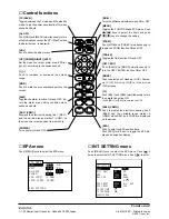
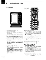
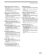
TRANSMIT/SAVE SWITCH [TX (SAVE)] (p. 11)
Push to toggle between the TX mode and the
standby mode.
Push and hold for 0.5 sec. to turn the power save
function ON. The radar for TX interval scan is fixed
at 10 revolutions. (p. 14)
• Select the save time in FUNCTION menu.
o
DISPLAY BRILLIANCE SWITCH [BRILL] (p. 6)
Push [BRILL] to turn the brilliance adjustment menu
ON or OFF.
• The brilliance and contrast of the symbol, character and
illumination can be adjusted in [BRILL.] and [CONTR.]
of the [BRILL] menu independently.
• Positive or Negative selection is available in [DISP.]
menu.
• Pushing and holding [BRILL] for 1 sec. to turn the con-
trast and brilliance to the default setting.
!0
HEADING LINE OFF FUNCTION [HL OFF] (p. 11)
Push [ADJ] and [MENU] simultaneously to turn off
all indication except the PPI (Plan Position Indica-
tor) screen, temporarily.
!1
MENU SWITCH [MENU] (pgs. 7–9)
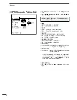
Push [MENU] to toggle the FUNCTION and EPA
menu. Push
[
]/
[
]
keys
to select the items and
push
[
]
/[
]
keys to change the setting.
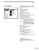
• Enter the “INT. SETTING” from the “EPA” menu.
• Enter the “SERVICE MAN” menu from the “INT SET-
TING MENU”.
!2
ZOOM FUNCTION [ZOOM] (p. 13)
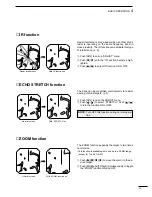
Push [MOB] and [TRAILS] simultaneously to toggle
the ZOOM function ON and OFF. ZOOM function
expands the target to 2 times normal.
• Move the cursor to the target, then turn the function ON.
• The screen zooms around the middle of the cursor and
own ship.
• This function is not available at
1
/
8
,
3
/
4
and 32 NM or
above ranges.
!3
TRAILS SWITCH [TRAILS] (p. 14)
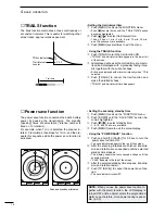
Push to toggle the trail function ON and OFF. This is
useful for watching other ship’s tracks, approx. rela-
tive speed etc.
• Trail Time can be set in FUNCTION menu.
!4
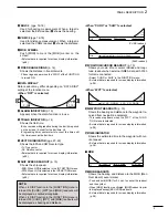
OFF CENTER FUNCTION [OFF CENT] (p. 12)
Push [ALM] and [MODE] simultaneously to turn
the OFF CENTER function ON or OFF.
• This function is not available at 32 NM or above ranges.
!5
MODE SWITCH [MODE]
Push to select one of Head-up (H UP), Course-up
(C UP), North-up (N UP) or True motion (TM)
screens.
• The North-up, Course-up and TM screens require ‘Ex-
ternal data’ (p. 38).
• TM screen is not available at 32 NM or above ranges.
!6
PARALLEL INDEX LINE FUNCTION [PI]
Push [EBL1] and [EBL2] simultaneously to turn the
parallel index line ON.
Push [EBL1] or [EBL2] to turn the line OFF.
•Push
[
]
/[
]
keys
to rotate the lines, and push
[
]/
[
]
keys
to adjust the line spaces.
!7
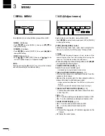
EBL2 (VRM2) SWITCH [EBL2 (VRM2)] (pgs. 16–18)
Push to display the Electronic Bearing Line 2
(EBL2) and the Variable Range Marker 2 (VRM2)
while EBL1 and VRM1 are displayed on the screen.
• Push [EBL2/VRM2] to toggle the center of VRM2 as fol-
lows.
Own ship
➔
Intersection of the EBL1 and VRM1
➔
OFF.
!8
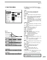
EPA SWITCH [EPA] (pgs.20–22)
Push to enter the EPA position data.
Push the [EPA] for 0.5 sec. to toggle the EPA dis-
play and navigation display.
• Push
[
]/
[
]/
[
]
/[
]
key to move the cross cursor on
the echo which you want to plot on the screen before
turning the function ON.
• Select “EPA” function ON in the “EPA” menu, set the ap-
propriate VECT, No. DISP, ALARM, CPA LIMIT and
TCPA LIMIT setting.
• External data is required for screen display information.
(p.38).
Summary of Contents for MR-570R
Page 3: ...INSTRUCTION MANUAL MARINE RADAR MR 570R ...
Page 36: ...30 9 INSTALLATION AND CONNECTIONS THIS PAGE IS INTENDED TO BE BLANK ...
Page 45: ...15 39 TEMPLATE 160 mm 6 5 16 91 mm 3 19 32 EX 2473 TEMPLATE ...
Page 46: ...40 ...
Page 47: ...Ship bow direction Radius is 6 mm 1 4 in EX 2474 Scanner unit template 45 5 mm 125 32 in ...
Page 48: ...90 5 mm 39 16 in 90 5 mm 39 16 in 150 5 mm 515 16 in 37 41 15 TEMPLATE ...
Page 49: ...1 1 32 Kamiminami Hirano ku Osaka 547 0003 Japan A 6014H 1EX q Printed in Japan 2001 Icom Inc ...

