2
PANEL DESCRIPTION
5
#0
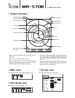
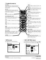
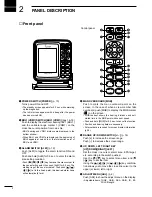
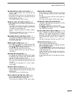
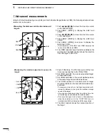
EBL1/2 (pgs. 16-18)
Used for bearing measurement. When a target is
selected, the EBL readout
#6
shows the bearing.
#1
VRM1/2 (pgs. 16-18)
Used for distance measurement. When a target is
selected, the VRM2 readout
@8
shows the distance.
#2
MOB SYMBOL
Push [MOB] to mark the [MOB] marker on the
screen.
• External data is required for screen display information.
(p.38).
#3
FIXED RANGE RINGS (p. 16)
Shows the distance in fixed intervals.
• These rings appear when the “RING” of the FUNCTION
is turned ON.
‘
DATA DISPLAY
Data readout may differ depending on “DATA DISP”
setting of the function menu.
• When “OFF” is selected;
#4
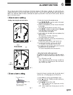
ALARM INDICATOR (p. 19)
Appears when the alarm function is in use.
#5
TRAILS INDICATOR (p. 14)
Shows the trail time.
• Echo remains with gradation during the trail time period
on the screen. (Except for the trail time;
∞
)
• Progressing time counter starts to count the time until
the timer reaches the trail time.
#6
VECTOR INDICATOR (pgs. 20-22)
Shows the EPA and OWN vector type.
• Tv: True vector
• Rv: Relative vector
• External data is required for screen display information.
(p.38).
#7
SHIP SPEED READOUT (p. 15)
Shows the ship speed.
• SOG: When GPS is selected in the INT. SETTING menu.
• STW: When LOG is selected in the INT. SETTING menu.
• External data is required for screen display information.
(p.38).
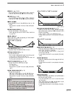
• When “CURS” or “SHIP” is selected;
#8
POSITION/CURSOR READOUT (p. 15)
Shows your own ship or cursor latitude and longi-
tude readout when external NMEA data with 0183
format is connected.
• Select ‘CURS’ or ‘SHIP’ in the FUNCTION menu.
• External data is required for screen display information.
(p.38).
• When “WPT” is selected;
#9
WAYPOINT READOUTS (p. 15)
Shows the bearing and distance to the waypoint re-
ceived from navigation equipment.
• This readout appears when the “WPT” of the FUNC-
TION menu is selected.
• External data is required for screen display information.
(p.38).
$0
TIME INDICATOR
Shows the estimated time to the waypoint with cur-
rent speed.
• External data is required for screen display information.
(p.38).
‘
MOB
$1
MOB READOUTS
Shows the bearing and distance to the MOB (Man
Over Board) event marker.
• Push and hold [MOB] for 0.5 sec. to cancel the readout
and the symbol.
• When [MOB] function is activated, [MOB] readout is prior
to displayed except [EBL/VRM] readouts.
• External data is required for screen display information.
(p.38).
POSN
34º38637N
SOG
Tv
135º33.209E
WPT
34
˚
42.000N
SOG
Tv
135
˚
29.000E
MOB
R
3087
˚
SOG
Tv
O:04
4.365NM
SOG
Tv
AL
TR
0’08
#4
#5
#6
#7
17.7KT
CURS
R
0398º
SOG
Tv
O:09
2.068NM
(CURS readout)
(SHIP readout)
NOTE:
When L/L DISP function in the [FUNCTION] menu is
turned ON, [CURS], [WPT] and [MOB] readouts will
be displayed as Latitude/Longitude.
When L/L DISP function in the [FUNCTION] menu is
turned OFF, [CURS], [WPT] and [MOB] readouts will
be displayed as bearing and distance.
Summary of Contents for MR-570R
Page 3: ...INSTRUCTION MANUAL MARINE RADAR MR 570R ...
Page 36: ...30 9 INSTALLATION AND CONNECTIONS THIS PAGE IS INTENDED TO BE BLANK ...
Page 45: ...15 39 TEMPLATE 160 mm 6 5 16 91 mm 3 19 32 EX 2473 TEMPLATE ...
Page 46: ...40 ...
Page 47: ...Ship bow direction Radius is 6 mm 1 4 in EX 2474 Scanner unit template 45 5 mm 125 32 in ...
Page 48: ...90 5 mm 39 16 in 90 5 mm 39 16 in 150 5 mm 515 16 in 37 41 15 TEMPLATE ...
Page 49: ...1 1 32 Kamiminami Hirano ku Osaka 547 0003 Japan A 6014H 1EX q Printed in Japan 2001 Icom Inc ...

