


3
2
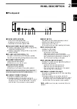
PANEL DESCRIPTION
1
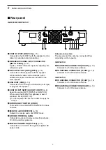
CONT I/O PORT [CONT I/O]
(p. 15)
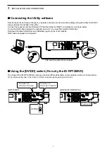
Connects to the ID-RP2C with the supplied control
cable for serial data communications.
2
REFERENCE SIGNAL INPUT CONNECTOR
[REF IN 10 MHz]
(p. 16)
Inputs a 10 MHz reference signal for adjusting the
reference signal.
3
RPT1/RPT2 PORT [RPT1]/[RPT2]
(p. 16)
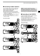
Connects to other repeaters with the supplied
control cable for data communications, when
additional repeater modules are installed in the
local repeater.
4
USB PORT [USB]
(p. 16)
Connects to a PC through a USB cable (A - B type)
to program the repeater.
5
CONT I/O RPT SWITCH [CONT I/O RPT]
(p. 8)
Select to use the [RPT1]/[RPT2] or [CONT I/O].
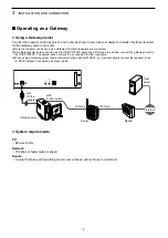
When using the ID-RP2C as gateway or assist
controller, set to [CONT I/O].
L
Turn the repeater OFF and then restart it to apply the
change.
6
DV/DD SELECT SWITCH [DV/DD]
This switch on the ID-RP2010V/ID-RP4010V does
not work.
7
SERVICE JACK [SERVICE]
(p. 16)
Outputs the receive audio and DTMF tones.
8
GROUND TERMINAL [GND]
Connects to a ground to prevent electrical shocks,
TVI, BCI and other problems.
9
POWER CONNECTOR [DC13.8V]
(p. 15)
Connects to a 13.8 V DC through the supplied DC
power cable.
Antenna connectors:
The placement of the antenna connector differs
depending on the repeater.
ID-RP2010V:
10
RX ANTENNA CONNECTOR [RX ANT]
(p. 16)
Connects to a 50 Ω receive antenna.
11
TX ANTENNA CONNECTOR [TX ANT]
(p. 16)
Connects to a 50 Ω transmit antenna.
ID-RP4010V:
10
TX ANTENNA CONNECTOR [TX ANT]
(p. 16)
Connects to a 50 Ω transmit antenna.
11
RX ANTENNA CONNECTOR [RX ANT]
(p. 16)
Connects to a 50 Ω receive antenna.
1
3
4
2
9
10
11
7
5
■
Rear panel
ID-RP2010V/ID-RP4010V:
6
8
Summary of Contents for ID-RP2010V
Page 23: ...MEMO...