


2
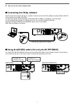
1
2
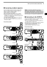
3
4
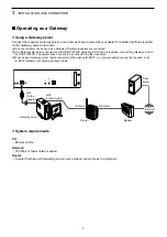
5
6
7
8
9
10
11
12
13
14
15
16
17
18
19
20
21
2
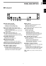
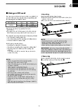
PANEL DESCRIPTION
1
POWER SWITCH [POWER]
• Push to turn the repeater ON.
L
Lights green when the repeater is ON.
• Hold down to turn the repeater OFF.
2
HIGH/LOW POWER SELECT SWITCH [H/L]
z
Sets the output power to High (25 W) or Low (2.5 W).
(ID-RP2010V/ID-RP4010V)
z
Sets the output power to High (10 W) or Low (1.0 W).
(ID-RP1200VD)
3
SD CARD SLOT [SD CARD] (p. 10)
Accepts an SD card. Used for firmware updates,
importing and exporting setting data and voice data.
4
TRANSMIT INDICATOR [TX]
Lights red while transmitting.
L
Blinks when an error has occurred.
5
RECEIVE INDICATOR [RX]
Lights green while receiving.
L
Blinks when the firmware is successfully updated.
NOTE:
Both [TX] and [RX] blinks at the same time
when the repeater is reset to the default value.
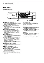
6
ETHERNET CONNECTOR [LAN 1]
Connects to a Gateway server PC.
L
If multiple repeaters are connected, and the ID-
RP1200VD operating in DD mode is included, connect
the gateway server to the ID-RP1200VD. The system
does not work if it is connected to other repeaters.
7
RESET SWITCH
The switch used for special operation such as
resetting the repeater, and so on.
L
Push using the tip of the pen.
L
The switch is also used when updating the firmware.
8
LTE STATUS [STATUS]*
Indicates the LTE status.
L
About the LED indication
• Lights while communicating.
• Blinks while registering to an LTE network.
• Slowly blinks when a communication failure occurs.
• Does not light when SIM cards are not inserted, or
the LTE connection setting is not applied.
9
LTE ANTENNA INDICATOR [ANT]*
Indicates the relative receive signal strength level.
L
About the LED indication
• Lights when the signal strength is good.
• Blinks when the signal strength is poor.
• Does not light when out of service ,or the repeater
cannot connect to an LTE network.
10
ETHERNET CONNECTOR [LAN 2] *
Connects to a Gateway server PC when operating
in the LTE mode.
L
If multiple repeaters are connected, and the ID-
RP1200VD operating in DD mode is included, connect
the gateway server to the ID-RP1200VD. The system
does not work if it is connected to other repeaters.
*
8
,
9
, and
10
are used only when an optional LTE unit is
installed.
1
2
3
4 5
7
8 9
10
6
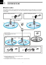
■
Front panel
Summary of Contents for ID-RP2010V
Page 23: ...MEMO...


