background image

INSTRUCTION MANUAL

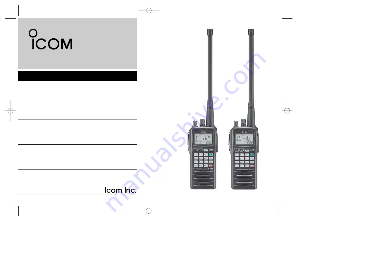
iA6

iA24

VHF AIR BAND TRANSCEIVER

This device complies with Part 15 of the FCC
Rules. Operation is subject to the condition
that this device does not cause harmful inter-
ference.

IC-A24

IC-A6

IC-A24_A6-5.qxd  2007.04.23  4:31 PM  Page i

Summary of Contents for IC-A24

Page 1: ...A24 VHF AIR BAND TRANSCEIVER This device complies with Part 15 of the FCC Rules Operation is subject to the condition that this device does not cause harmful inter ference IC A24 IC A6 IC A24_A6 5 qxd 2007 04 23 4 31 PM Page i ...

Page 2: ... radio without a proper antenna attached as this may damage the radio and may also cause you to exceed FCC RF exposure limits A proper antenna is the antenna supplied with this radio by the man ufacturer or antenna specifically authorized by the manufacturer for use with this radio DO NOT transmit for more than 50 of total radio use time 50 duty cycle Transmitting more than 50 of the time can caus...

Page 3: ...XPLICIT DEFINITIONS SUPPLIED ACCESSORIES Accessories included with the transceiver Qty q Antenna 1 w Belt clip 1 e Handstrap 1 r Battery pack or battery case 1 t Wall charger 1 y Carrying case 1 u Headset adapter 1 The battery pack wall charger headset adapter or carrying case may differ depending on version Some versions do not include a battery pack wall charger headset adapter or carrying case ...

Page 4: ...may flow into nearby metal objects such as a necklace etc Therefore be careful when carrying with or placing near metal objects carrying in handbags etc DO NOT allow children to play with any radio equipment containing a transmitter DO NOT operate the transceiver near unshielded electrical blasting caps or in an explosive atmosphere AVOID using or placing the transceiver in direct sunlight or in a...

Page 5: ... tone 11 4 MEMORY OPERATION 12 15 Memory channel selection 12 Transferring memory contents 12 Programming a memory channel 13 Memory names 14 Clearing the memory contents 14 5 SCAN OPERATION 16 17 Scan types 16 COM band scan 16 Memory scan 16 Weather channel scan U S A version only 17 TAG channels 17 6 VOR NAVIGATION IC A24 only 18 24 VOR indications 18 VOR functions 19 Flying to a VOR station 20 ...

Page 6: ...1 1 PANEL DESCRIPTION Panel description e r t u y i o Microphone Speaker 6 5 7 q w 1 0 2 3 4 WX ALERT IC A24 7 WX ALERT 7 IC A6 IC A24_A6 5 qxd 2007 04 23 4 31 PM Page 2 ...

Page 7: ...WX ALERT then rotate DIAL to se lect the squelch level 24 squelch levels and squelch open 0 are available Push then push SQL WX ALERT to turn the WX alert function ON or OFF i POWER SWITCH PWR pgs 9 28 Push and hold for 2 sec to turn the power ON or OFF While pushing and holding MR MW push PWR to enter the cloning function mode o EXTERNAL SPEAKER AND MICROPHONE JACKS MIC SP p 34 Connects an OPC 49...

Page 8: ...ery pack or to operate by external power supply see right illustration 5 MEMORY MODE KEY MR MW pgs 12 15 Push to call the memory channel mode Push then push MR MW to program the contents into the memory channels 6 ENTER KEY ENT WX pgs 8 14 Push to enter the numeral input Enters consec utive zero digits p 8 Push then push ENT WX to enter the weather channel selection mode U S A version only p 8 Pus...

Page 9: ... 3 FROM to change the course indicator characteristics to FROM flag in the DVOR display in NAV band p 19 1 Corrects the deviation while using FROM flag 1 Push then push 4 CDI to select the CDI dis play from the CDI display in NAV band p 19 1 Push then push 5 DUP W to set the duplex frequency in NAV band for U S A version only p 24 1 Push then push 6 DUP to turn the duplex function ON and OFF in NA...

Page 10: ... NAV mode DUP blinks while setting the duplex frequency t LOW BATTERY INDICATOR p 10 Appears when the battery is nearing exhaustion The at tached battery pack requires recharging Appears and flashes when battery replacement is nec essary y LOCK INDICATOR p 11 Appears while the lock function is in use u FREQUENCY DISPLAY pgs 8 14 Shows the operating frequency Shows the channel name when the memory ...

Page 11: ...CATOR p 9 Appears while the ANL Automatic Noise Limiter function is in use 3 COURSE DEVIATION NEEDLES IC A24 only pgs 18 22 Indicates the deviation between the desired course and your actual flying course every 2 degrees 4 COURSE INDICATORS IC A24 only p 19 Indicates where your aircraft is located on a VOR radial in DVOR mode Indicates where your desired course is located on a VOR radial in CDI mo...

Page 12: ...ntly attaches to your belt Attach the belt clip with the supplied screws as below NOTE Use the supplied screws only DBattery pack replacement Before replacing the battery pack push PWR for 2 sec to turn the power OFF Slide the battery release button forward then pull the battery pack upward with the transceiver facing away from you Supplied screws 2 ACCESSORY ATTACHMENT IC A24_A6 5 qxd 2007 04 23 ...

Page 13: ...mber appears on the function dis play w Rotate DIAL to set the desired frequency To select the 1 MHz tuning step push then rotate DIAL Push again to return the normal tuning Setting a squelch level The transceiver has a noise squelch circuit to mute undesired noise while receiving no signal q Push SQL WX ALERT then rotate DIAL to select the squelch level SQL 0 is open squelch and SQL 24 is tight s...

Page 14: ... ANL function ON OFF appears on the display while the ANL function is ON Transmitting q Set the desired frequency in COM band using DIAL or keypad COM band frequency range 118 00 136 975 MHz w Push and hold PTT to transmit indicator appears e Speak into the microphone at a normal voice level DO NOT hold the transceiver too close to your mouth or speak too loudly This may distort the signal r Relea...

Page 15: ...o select the deleting recall channel wPush then push CLR DEL for 2 sec to delete it e g Deletes r0 recall channel which is stored 120 450 MHz and r1 recall channel stores 123 450 MHz DReplaces the stored recall channel qPush or to select the recall channel to be re placed wPush then push or to replace it Replaces the selected channel into the previous channel when is pushed and then is pushed Repl...

Page 16: ...accidental function activation q Push then push 7 to turn the lock function ON appears w To turn the function OFF repeat step q above disappears Side tone function When using an headset other manufacture s products the transceiver outputs your transmitted voice to the headset for monitoring Connect the optional headset with the transceiver when using this function OPC 499 HEADSET ADAPTER and heads...

Page 17: ...de e Push 2 appropriate digit key 00 to 19 to select the de sired memory CH number If no memory CH is programmed in the selected BANK no memory CH selection is available NOTE Comments appear first when programmed how ever the transceiver can be programmed by your dealer to show the operating frequency first Push MR MW to display the comment in this case Transferring memory contents This function t...

Page 18: ...ory writ ing mode M Memory BANK and memory channel number are blink r Rotate DIAL to select the desired memory channel num ber Push then push 0 BANK and rotate DIAL to select the BANK number if desired Push CLR DEL ENT WX or push then push 0 BANK to exit the BANK selection mode t Push ENT WX to program the information into the chan nel and return to the frequency mode Weather channel U S A version...

Page 19: ...isplayed as _ To move the cursor forwards or backwards use DIAL y Push ENT WX to program the name Flashing the memory name stops When no name is programmed the display shows the operating frequency To clear the entered memory names push CLR DEL before pushing ENT WX NOTE When programming the memory name to the pro grammed memory channel already operate as follow q Operate same as Transferring memo...

Page 20: ...ush EXAMPLE Programming 125 000 MHz into memory BANK 1 memory channel 17 with AIR 23 as a comment NOTE Push then push 0 BANK and then rotate DIAL to select the BANK number if desired Push CLR DEL to exit the BANK selection mode IC A24_A6 5 qxd 2007 04 23 4 32 PM Page 16 ...

Page 21: ...te DIAL to set the squelch level to the point where noise is just muted e Push then push ANL SCAN to start the scan When a signal is received the scan pauses until it disappears To change the scanning direction rotate DIAL r To stop the scan push CLR DEL NOTE Program 2 or more memory channels to start memory scan WEATHER CHANNEL SCAN Repeatedly scans all TAG weather channels Weather channels are a...

Page 22: ... tively The TAG channel function is only available during scan operation q Push MR MW to select memory mode or push then push ENT WX to select a weather channel w Select the desired memory channel to be a TAG chan nel Push then push 0 BANK and rotate DIAL to select the BANK number if desired Push CLR DEL to exit the BANK se lection mode e Push then push 9 TAG to set a TAG TAG appears Non TAG chann...

Page 23: ...of the IC A24 General VOR equipment To from flag indicator CDI MODE Course indicator Course indicator Course deviation needles Overflow indicator Push F then 4 CDI Push F then 1 DVOR To from flag indicator Course indicator Course deviation needle To from flag indicator Two degree deviation marks 5 6 IC A24_A6 5 qxd 2007 04 23 4 32 PM Page 19 ...

Page 24: ...ROM or vice versa respectively NOTE When using the TO flag and passing through the VOR station the TO flag changes to the FROM flag automatically When turning power ON the FROM flag is selected automati cally DSelecting the next VOR station when using CDI mode when using the course deviation needle q Push then push 1 DVOR to select the DVOR mode w Push the keypad or rotate DIAL to set the next VOR...

Page 25: ...the desired VOR signal cannot be received NOTE When the CDI mode is selected the operating fre quency cannot be changed To set the operating fre quency select the DVOR mode in advance r The course deviation needle appears when your aircraft is off course from the VOR station Ω or appears to indicate your aircraft is off course to the right or left respectively Correct your course until Ω or disap ...

Page 26: ...0 70 80 90 100 110 120 130 140 150 160 170 180 190 200 210 220 230 240 250 260 270 280 290 300 310 320 330 340 350 N Magnetic north Aircraft should be heading 40 Aircraft heading 46 6 off course Flown course 123 65 VORTAC SEATTLE 116 8 Ch 115 SEA THE AIRCRAFT IS OFF COURSE NOTE The course deviation indica tor appears when the aircraft is off course In this example the aircraft is 6 degrees off cou...

Page 27: ...0 degrees to the desired course if the overflow indica tor appears on the left side select a heading minus 10 degrees Crosschecking position q Select 2 VOR stations on your aeronautical chart w Push the keypad or rotate DIAL to set the frequency of one of the VOR station in the DVOR mode The course indicator shows course deviation from the VOR ra dial Note the radial you are on e Push the keypad o...

Page 28: ... 180 190 200 210 220 230 240 250 260 270 280 290 300 310 320 330 340 350 N Magnetic north VOR station 0 10 20 30 40 50 60 70 80 90 100 110 120 130 140 150 160 170 180 190 200 210 220 230 240 250 260 270 280 290 300 310 320 330 340 350 113 4 Ch 81 OLM VORTAC OLYMPIA 116 8 Ch 115 SEA 123 65 VORTAC SEATTLE CROSSCHECKING POSITION IC A24_A6 5 qxd 2007 04 23 4 32 PM Page 24 ...

Page 29: ...ter setting a frequency The displayed frequency returns to the NAV band frequency DOperating the duplex function q Set the desired frequency in NAV band NAV band frequency range 108 00 117 975 MHz w Push then push 6 DUP to turn the duplex function ON DUP appears on the function display e Push and hold PTT to transmit at the pre programmed transmit frequency r Release PTT to return to receive t Pus...

Page 30: ... area or contact your dealer Battery cautions CAUTION NEVER insert battery pack transceiver with the battery pack attached with wet or soiled into the charger This may result in corrosion of the charger terminals or damage to the charger The charger is not waterproof and water can easily get into it NEVER incinerate used battery packs Internal battery gas may cause an explosion NEVER immerse batte...

Page 31: ... the battery case from the transceiver wInstall 6 AA LR6 size Alkaline batteries Be sure to observe the correct polarity CAUTION When installing batteries make sure they are all the same brand type and capacity Also do not mix new and old batteries together Keep battery contacts clean It s a good idea to clean bat tery terminals once a week Wall charger To DC 11V IC A24 A6 with the attached batter...

Page 32: ...ollowing are additionally re quired Six AD 101 charger adapters An AC adapter BC 124 or the DC power cable OPC 656 NOTE Attach the spacer Spacer B C to the adapter Spacer A with orientation as illustrated below AD 99 supplied with AD 101 AD 101 optional AC adapter Supplied screws with AD 101 BC 119N optional IC A24 A6 BP 209N BP 210N BP 211N Turn power OFF Spacer A Spacer B C Check orientation and...

Page 33: ...sceiver s display r When cloning is finished turn power OFF then ON again to exit cloning mode NOTE DO NOT transfer the data from IC A24 to IC A6 when the data contains the NAV band data In such case cloning error may occur DCloning using PC Data can be cloned to and from a PC Microsoft Windows 98 98SE Me 2000 XP using the optional CS A24 CLONING SOFTWARE and the optional OPC 478 RS 232C type or O...

Page 34: ...de p 8 The battery is exhausted Recharge the battery pack pgs 25 27 Operating frequency or Lock function is activated Push then push 7 p 11 memory channel can not be changed Scan does not start All memory channels in the selected bank Set the TAG settings of desired p 17 are not programmed as TAG channels channels Squelch is open Set the squelch level to tighten p 8 There is not more than 2 memori...

Page 35: ...6 dB except operating frequency 62 5 kHz range Modulation distortion 4 Less than 10 at 85 3 dB Mod Harmonics spurious emissions 4 Less than 26 dBm Microphone connector 3 conductor 2 5 d mm 1 10 more than 100 kΩ DReceiver Receive system Double conversion superheterodyne Intermediate frequencies 1st 30 05 MHz 2nd 450 kHz Sensitivity VOR AM 6 dB S N 3 dBµ typical COM AM 6 dB S N 3 6 dBµ typical COM A...

Page 36: ...CHARGER For rapid charging of BP 209N Ni Cd and BP 210N Ni MH D BELT CLIPS MB 103 BELT CLIP The same as supplied with the transceiver MB 86 SWIVEL BELT CLIP Belt clip for swivel type MB 96F 96N LEATHER BELT HANGER MB 96F Attaches with the supplied belt clip Fixed type MB 96N Belt hanger for swivel type D DC CABLES CP 20 CIGARETTE LIGHTER CABLE Charges the battery pack through a cigarette lighter s...

Page 37: ...om the VOR station Push then push 1 DVOR to exit the CDI mode r t VOR NAVIGATION Flying to a VOR station Continued n SCAN pgs 16 17 q w e Push CLR DEL MR MW or push 0 then push ENT WX to select the frequency memory or WX CH mode Push then push ANL SCAN to start scanning Push CLR DEL to cancel the scan ning Push then push 2 TO or 3 FROM to change the to from flag Push then push 2 TO to se lect TO P...

Page 38: ...d BANK number BANK 0 to 9 Push then push 0 BANK or push ENT WX to set the BANK number and exit the BANK selec tion mode q w e Push CLR DEL to exit the BANK selection mode BANK number and memory CH number disappears as frequency mode is automatically selected and the memory contents are transferred n MEMORY OPERATION p 13 q w e r t Push CLR DEL to select the frequency mode or push then push ENT WX ...

Page 39: ...e Side tone function p 11 when setting the side tone level PTT OPC 499 IC A24 A6 PTT switch HEADSET Must be purchased separately Use a PTT switch with a 3 5 mm 1 8 diameter plug if required 12 13 NOTICE Some headsets do not work properly when used with the IC A24 A6 Therefore ask your dealer for details about headsets compatible for operation with the IC A24 A6 with the headset IC A24_A6 5 qxd 200...

Page 40: ...1 1 32 Kamiminami Hirano ku Osaka 547 0003 Japan Printed on recycled paper with soy ink A 6403D 1EX t Printed in Japan 2004 2007 Icom Inc IC A24_A6 5 qxd 2007 04 23 4 32 PM Page 36 ...

Reviews: