background image

T-CAM 80 P-SERIES/T-CAM 160 XT USER MANUAL

13

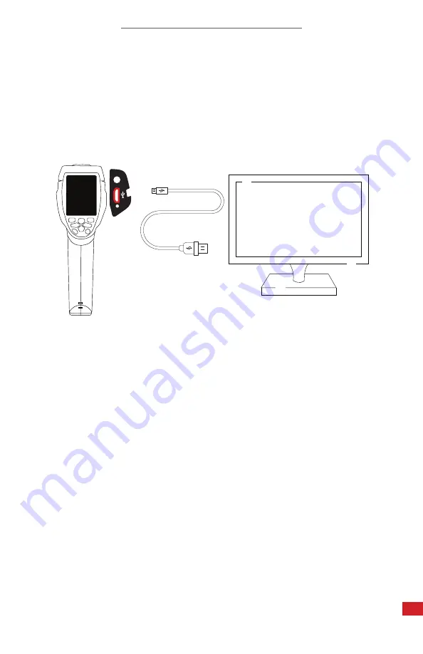
8-3 Charging Instructions

IF YOU DO NOT USE THE IMAGER FOR A LONG PERIOD OF TIME, 

PUT  THE  DEVICE  IN  A  COOL  AND  DRY  ENVIRONMENT.  THE 

BATTERY WILL DISCHARGE OVER TIME; THEREFORE, THE IMAGER 

SHOULD BE CHARGED OCCASIONALLY TO PREVENT DAMAGE TO 

THE BATTERY OR THE DEVICE.

ENSURE  THE  IMAGER  IS  NEAR  ROOM  TEMPERATURE  BEFORE 

CHARGING THE DEVICE. DO NOT CHARGE IN EXTREMELY HOT OR 

COLD  AREAS.  THE  BATTERY  CAPACITY  MAY  BE  DECREASED  IF 

CHARGED IN AN EXTREME TEMPERATURE ENVIRONMENT.

CHARGE  THE  BATTERY  FOR  A  MINIMUM  OF  1.5  HOURS  BEFORE 

USING.  ICI  DOES  NOT  RECOMMEND  CHARGING  THE  DEVICE 

WHILE IT IS CONNECTED TO A TRIPOD. LAY DEVICE FACE DOWN 

ON A FLAT AND STABLE DESK OR TABLE WHILE CHARGING.

A.

Plug the Micro-USB end of 

theUSB cable into the right 

side of the T-Cam device.

B.

Plug the other end of the 

USB cable into an available 

USB port on a computer.

Audio

WHEN  USING  A  COMPUTER  FOR  CHARGING  THE  COMPUTER 

SHOULD BE POWERED ON.

Summary of Contents for T-CAM 80 XT Series

Page 1: ...SWITCHING THE UNIT ON IMPORTANT SAFETY INFORMATION INSIDE 2105 W Cardinal Dr Beaumont TX 77705 ICI cameras fall under US Federal Law and Export Control For more information contact us 409 861 0788 sales infraredcameras com www infraredcameras com Edit Text Out Ind Industry ...

Page 2: ...CCURATE BUT ARE PRESENTED WITHOUT WARRANTY OF ANY KIND NOTWITHSTANDING ANY OTHER WARRANTY HEREIN ALL DOCUMENT FILES AND SOFTWARE ARE PROVIDED AS IS WITH ALL FAULTS ICI DISCLAIMS ALL WARRANTIES EXPRESSED OR IMPLIED INCLUDING WITHOUT LIMITATION THOSE OF MERCHANTABILITY FITNESS FOR A PARTICULAR PURPOSE AND NONINFRINGEMENT OR ARISING FROM A COURSE OF DEALING USAGE OR TRADE PRACTICE THE SOFTWARE LICENS...

Page 3: ...er Notice 3 Intended Use 4 Safety Information 5 Intended Use 6 Technical Specifications 7 Structure 8 Package Includes 9 Quick Start Instructions 10 Operations Instructions 11 PC Software 12 Cleaning and Maintenance 13 Troubleshooting 14 About ICI 4 4 4 5 6 6 7 9 10 14 33 34 35 36 ...

Page 4: ... be updated from time to time Please contact us to get the latest version of the manual 2 3 Scope of Application This manual is applicable to multiple devices in the T Cam series which means that some content in this manual may not be applicable a specific model This manual may contain technical inaccuracies or typographical errors 3 Intended Use The T Cam 80 T Cam 160 XT Series cameras are handhe...

Page 5: ...put holes in the device or battery with objects Do not hit the device or battery with a hammer Do not solder directly onto the battery Do not step on the battery or apply strong impacts or shocks to it Do not get water or salt water on the battery or permit the battery to get wet Do not put the device or battery in direct sunlight or other high temperature locations Always charge the battery in th...

Page 6: ... C to 70 C 40 F to 158 F Humidity 5 to 95 non condensing Accuracy 0 5 C 0 9 F Pixel Operability 99 Drop Test 2 m 6 56 ft Dimensions without lens 224 mm x 77 mm x 96 mm L x W x H 5 mm 8 81 x 3 03 x 3 78 L x W x H 0 02 Power DC 5V Battery Li ion 4 hours rechargeable Weight 500 g 1 10 lbs Interface Mini USB Micro HDMI audio Video Format MP4 1280 x 960 30 fps Video Out Micro HDMI Image Format JPG Imag...

Page 7: ...initions of Interface 1 Camera lens cover 2 Lens focus adjuster 3 Trigger 4 LCD display 5 a b c d e f g h Buttons Menu Select Lock Close Up Zoom out Down Zoom in Right LED flashlight Left Laser Files Browse Power 6 Battery bay 7 Holes for non slip strap Left Right a c b g d h f e ...

Page 8: ...AM 160 XT USER MANUAL 8 8 LED light 9 Visual camera 10 Laser pointer 11 Infrared camera lens 12 Hole for tripod insertion 13 Charge light 14 USB Charger input terminal 15 Audio Microphone 16 HDMI output 17 MicroSD card slot ...

Page 9: ...T CAM 80 P SERIES T CAM 160 XT USER MANUAL 9 Software CD T Cam device Micro USB to USB Cable 7 Package Includes ENSURE ALL SYSTEM EQUIPMENT AND COMPONENT ITEMS ARE PRESENT BEFORE BEGINNING INSTALLATION ...

Page 10: ...SON S TO BE IMAGED TO ENSURE THE EQUIPMENT WILL NOT BE MOVED OR KNOCKED DOWN USING A DIVIDING BARRIER WILL HELP KEEP TRIPODS SEPARATE FROM THE PATH 8 Quick Start Instructions 8 1 Tripod Setup A or Mount the fully charged T Cam to a tripod using the 20 mount The T Cam can be used as a handheld device ...

Page 11: ...NDS PRESS AND HOLD THE POWER BUTTON FOR MORE THAN TWO SECONDS TO SHUT DOWN THE CAMERA THE THERMAL IMAGER NEEDS SUFFICIENT WARM UP TIME FOR THE MOST ACCURATE TEMPERATURE MEASUREMENTS AND BEST IMAGE QUALITY THIS TIME CAN OFTEN VARY BY ENVIRONMENTAL CONDITIONS IT IS BEST TO WAIT A MINIMUM OF 10 MINUTES FOR THE DEVICE TO COMPLETELY WARM UP ...

Page 12: ...CONTACT PINS MUST BE INSERTED FIRST IF THERE IS RESISTANCE FLIP THE CARD AROUND AND TRY AGAIN TO EJECT THE MEMORY CARD PRESS UNTIL A CLICK IS HEARD AND THEN RELEASE MEMORY CARD WILL BE EJECTED 8 2 Memory Card Installation A Insert the Micro SD Card into the side of the T Cam device until a clicking sound is heard ...

Page 13: ...CE DO NOT CHARGE IN EXTREMELY HOT OR COLD AREAS THE BATTERY CAPACITY MAY BE DECREASED IF CHARGED IN AN EXTREME TEMPERATURE ENVIRONMENT CHARGE THE BATTERY FOR A MINIMUM OF 1 5 HOURS BEFORE USING ICI DOES NOT RECOMMEND CHARGING THE DEVICE WHILE IT IS CONNECTED TO A TRIPOD LAY DEVICE FACE DOWN ON A FLAT AND STABLE DESK OR TABLE WHILE CHARGING A Plug the Micro USB end of theUSB cable into the right si...

Page 14: ...the battery is full charged ENSURE THE IMAGER IS NEAR ROOM TEMPERATURE BEFORE CHARGING THE DEVICE DO NOT CHARGE IN EXTREMELY HOT OR COLD AREAS THE BATTERY CAPACITY MAY BE DECREASED IF CHARGED IN AN EXTREME TEMPERATURE ENVIRONMENT THE THERMAL IMAGER NEEDS SUFFICIENT WARM UP TIME FOR THE MOST ACCURATE TEMPERATURE MEASUREMENTS AND BEST IMAGE QUALITY THIS TIME CAN OFTEN VARY BY ENVIRONMENTAL CONDITION...

Page 15: ...12 1 2 3 4 5 6 8 9 10 1X 7 ONLY THE CENTER POINT TEMPERATURE IS ACTIVATED IN THE PRESENTED IMAGE ABOVE ADDITIONAL TARGETS WILL APPEAR WHEN THE HOT SPOT AND COLD SPOT TEMPERATURE POINTS ARE ENABLED IN THE SETTINGS ONLY THE CENTER POINT TEMPERATURE IS ACTIVATED IN THE PRESENTED IMAGE ABOVE HOT SPOT AND COLD SPOT TEMPERATURE POINTS ARE ALSO AVAILABLE IN THE SETTINGS MENU WHEN AN SD CARD IS NOT INSTAL...

Page 16: ...array and lens focal length Example If the thermal imager uses a 9mm lens because the pixel size of the detector is 34µm then horizontal FOV is 17 vertical FOV is 17 the IFOV is 34 µm 9 mm 3 78 mrad D S theoretical 1 IFOV theoretical 265 1 D Smeasure 1 IFOV measure is the spot size needed to provide an accurate temperature measure Typically D Smeasure is 2 to 3 times smaller than D S theoretical w...

Page 17: ...n and the image will zoom out 10 Press and hold for continuous zooming Press the Zoom In and image zooms in 10 Press and hold for continuous zooming When zoomed in or zoomed out the zoom factor displays in the upper status bar 9 8 Non uniformity Correction NUC Non uniformity correction NUC is used to compensate for the non uniformity of detector pixels or other optical interference A common need f...

Page 18: ... Close to exit without changes All objects radiate infrared energy The amount of energy radiated varies based on the actual surface temperature and the surface emissivity of the object The Thermal imager senses the infrared energy from the surface of the object and uses this data to calculate an estimated temperature value Many common objects and materials such as painted metal wood water skin and...

Page 19: ...Using the offset factor the reflection is calculated out due to the low emissivity improving temperature measurements In most cases the reflected temperature is identical to the ambient air temperature The reflected temperature has little effect on objects with high emissivity The reflected temperature can be set individually Follow these steps to get the right value for the reflected temperature ...

Page 20: ...ht desired image mode 5 Press Select to confirm and auto close Menu Press Close to exit without changes 9 13 Alignment When using AUF Mix and Fusion modes it is important to ensure the alignment distance is set correctly to receive the best image Align the images as follows 1 Press the Menu button 2 Highlight Settings from the Menu 3 Press the Select button A sub menu will open 4 Highlight Alignme...

Page 21: ...ain Control AGC and Manual Auto level and span are decided automatically by the minimum and maximum temperatures detected by the device Manual level and span are decided by the user input values The AGC function is enabled by default and automatically assists users in fine tuning image contrast If disabled users will be able to manually change the level and span Press the Lock button to change mod...

Page 22: ...on to enable the corresponding measurement The icon means the point is enabled The icon means it is disabled The Menu automatically closes after selection and must be reopened to verify changes have occurred THE THERMAL IMAGER NEEDS SUFFICIENT WARM UP TIME FOR THE MOST ACCURATE TEMPERATURE MEASUREMENTS AND BEST IMAGE QUALITY THIS TIME CAN OFTEN VARY BY ENVIRONMENTAL CONDITIONS IT IS BEST TO WAIT A...

Page 23: ... to exit without changes 8 Press Close to exit the menu 9 18 Alarm The Alarm enables threshold settings for temperature screening An audible will sound and the Level Span bar will flash red on screen if the threshold is exceeded Set the threshold as follows 1 Press the Menu button 2 Highlight Emissivity from the Menu 3 Press the Select button A sub menu will open 4 Highlight Alarm in the sub menu ...

Page 24: ...ATURE SCALE IS SELECTED WHEN MEASURING HIGH TEMPERATURE OBJECTS ENSURE THE TEMPERATURE RANGE IS SET TO THE 0 C TO 500 C RANGE TO OBTAIN THE MOST ACCURATE MEASUREMENT RESULTS 9 19 Reflective Temperature The reflective temperature is important for radiometric temperature measurement The imager has temperature compensation for reflective objects Set the reflective temperature to get the most accurate...

Page 25: ...ss Close to exit without changes 9 22 Temperature Unit There are three units to choose from C F and K By default the imager is set to measure temperatures in Celsius C Change the temperature scale as follows 1 Press the Menu button 2 Highlight Settings from the Menu 3 Press the Select button A sub menu will open 4 Highlight Temp Unit from the sub menu 5 Press the Select button 6 Highlight desired ...

Page 26: ...anges Item Parameter Value Measurement Center Spot Measurement off Hot Spot Measurement off Cold Spot Measurement off Parameters Emissivity 0 95 Reflective temperature 25 C Image Mode Infrared Palette Iron Adjustment Auto System Setting Language English HDMI Output off Laser off Lamp off Factory settings of the imager are as follows PERFORMING A FACTORY RESET ERASES CUSTOMIZED USER CONFIGURATIONS ...

Page 27: ... button to highlight the correct option 6 Press Up or Down button to modify the value of selected item 7 Press the Ok button to confirm and automatically close the Menu Press Cancel to exit without changes 9 25 Information 1 Press the Menu button 2 Highlight Settings from the Menu 3 Press the Select button A sub menu will open 4 Highlight Information from the sub menu 5 Press the Select button 6 P...

Page 28: ...button A sub menu will open 4 Highlight Auto power off from the sub menu 5 Press the Select button 6 Press the Up or Down button to highlight the desired setting 7 Press the Select button to confirm and automatically close the Menu Press Close to exit without changes 9 27 Volume 1 Press the Menu button 2 Highlight Settings from the Menu 3 Press the Select button A sub menu will open 4 Highlight Vo...

Page 29: ...hout saving the image 9 29 Video Menu In video mode the imager can capture hours of mp4 videos and saves the infrared data to the file 1 Insert earphone with microphone in order to record voices 1 Press the Trigger button and hold for about 2 seconds Video capture will start 2 To stop video capture press the Trigger button again 3 Press the Save button to save the video Press the Cancel button to ...

Page 30: ...e Right button to open next image 6 Press the Browse button to return files browser Press the Exit button to return to thermal capture interface 9 31 Play a Video 1 Press the Browse button The imager will display images and videos saved to the SD Memory Card 2 Press the Up Down Left and Right button to highlight a video 3 Press the Open button to enter the video player interface 4 To hear voices i...

Page 31: ...te the selected image Press the Up or Down button to highlight Delete Press the OK button to delete the selected file Delete all files Press the Up or Down button to highlight Delete all Press the OK button delete all files Exit the Browser Press the Up or Down button to highlight Exit press the OK button to return desktop 4 Press the Close button to return to the files Browser DELETED IMAGES AND ...

Page 32: ...tor or recording device using the HDMI video cable provided 2 Turn on the external HDMI monitor or device 3 Power on the imager 4 The thermal imager s display works simultaneously 5 When finished switch off the external device and disconnect the HDMI video cable from the thermal imager 9 33 USB Mode Connect the device to a computer using the USB cable A menu will open with two options Storage and ...

Page 33: ...oftware Installation 1 Insert CD into the CD drive of the computer and auto run installation or double click the setup exe from the CD files 2 Click Yes to allow changes to the computer 3 Click Next 4 Click I Agree to agree to terms of license agreement 5 Click Install 6 Click Finish 10 3 Running the Software Launch the software using the Start menu or by double clicking the desktop shortcut 10 4 ...

Page 34: ...iquid If the lens is still not clean replace the cloth and repeat the wiping process 11 2 Disinfecting the Camera Surface Do not use corrosive cleaning solutions on the optical glass components It is recommended to disinfect the camera surface regularly with a non corrosive sanitizing product Follow the directions provided by the manufacturer of the cleaning solution Adhere to the sanitation proto...

Page 35: ...eplace old battery Charge battery 12 3 No thermal image Open the lens cap 12 4 Camera out of focus Adjust focus ring 12 5 Temperature readings are incorrect Turn off the device then turn it back on Ensure the correct temperature range is selected The default temperature range is 20 C to 150 C 4 F to 302 F When measuring high temperature objects ensure the temperature range is set to the 0 C to 500...

Page 36: ... and sapphire optics we also build windows for enclosures as well as custom pan and tilt units We can even provide customizable explosion proof systems Our knowledge and experience stems from years of using infrared imaging and temperature measurement instruments to provide solutions to managers engineers scientists inspectors and operators in space power companies medical pulp and paper food indu...

Reviews: