background image

ICE RS26, powered by Brain OS  

|

  Gen2, v1.1217 – Content Subject to Change


Brain Corporation 

21

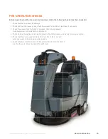
IF THE 

eStop

 BUTTON IS ENGAGED, ROBOT OPERATOR WILL NEED TO:

•  Disengage red eStop button by twisting up

•  Power cycle the machine

•  Return to the home location code and select route to run

SETTING CLEANING FUNCTIONS

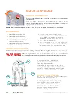
The following controls regulate the Brain-enabled scrubber’s cleaning functions. To obtain optimum cleaning 

performance, adjust brush pressure, solution flow and detergent dosage before use in manual or autonomous 

mode. When turning on machine, the controls will default to the factory settings.

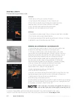
DETERGENT LEVELS INDICATOR AND CONTROL

WATER LEVEL INDICATOR AND CONTROL

SCRUBBER PRESSURE CONTROL

If any of the warning indicators outlined above appear, cease operating machine and correct problem. Additional 

detailed information about each error outlined below will appear on the Brain-enabled scrubber display.

To regulate amount of detergent released onto 
floor, press blue plus and minus buttons located 
on either end of the indicator to increase or decrease 
volume of detergent discharged. The machine 
allows between 0%-5% of detergent release.

Press the blue plus and minus buttons on either 
end of the indicator to increase or decrease 
the amount of water released. The machine 
allows between 0%-5% of water release.

Increase or decrease scrub pressure (or down force).

Summary of Contents for BE-MK1-RS26

Page 1: ...OPERATIONAL MANUAL ROBOTIC SCRUBBER ICE RS26 GEn2 Powered by BrainOS ...

Page 2: ......

Page 3: ...ing Brushes or Pads Mounting Side And Rear Squeegee Assemblies Filling the Solution Tank Filling Detergent Bottle 18 CONTROLS OVERVIEW Manual Functions Right Side Control Panel One Touch Button Vacuum Button Double Scrubbing Horn Momentary Key Ignition Directional Switch Emergency Stop Setting Cleaning Functions Detergent Levels Indicator and Control Water Level Indicator and Control Scrubber Pres...

Page 4: ...ation Codes 25 PRE OPERATION CHECKS 26 MANUAL MODE Start Up Brake Device Emergency Stop Buttons 27 AUTONOMOUS MODE Home Location Codes Establishing Home Locations Selecting Locations for the Home Location Code Scanning Home Location Codes Lost or Damaged Home Location Codes Teach Route Delete Route Execute Route 31 ROC ROBOT OPERATING CENTER Pairing Phone with Brain enabled Scrubber To Access the ...

Page 5: ...sembly Adjusting Side Skirt Height Removing Side Skirt Brake Release Removing the On Board Charger Removing Scrubber Brushes Inserting New Brush 39 BEST PRACTICES Tips for successful operation Establish Permanent Home Location s Inspect Maintain The Machine Running A Route Training A Route Cleaning Stowing Training Manual and Autonomous Mode Daily Maintenance Home Location Codes Start Up 42 TROUBL...

Page 6: ...es Machine should only be used by trained operators in controlled restricted environments approved by Brain Corp Brain Corp may provide additional training as to the intended use of the machine and the machine shall only be used in accordance with such training Use the machine in approved environments in accordance to the ASA and EULA Please see Autonomy Services Agreement ASA and Autonomous Navig...

Page 7: ...with reduced physical sensory or mental capabilities or lack of experience and knowledge Please see the ASA and EULA for further uses and restrictions If the machine operates autonomously in an area where people are present it is recommended that proper floor cleaning signage be used in accordance with standard floor cleaning practices The operator is responsible for the operation and use of each ...

Page 8: ...s may impair safety and potentially damage the machine The Machine is not designed or intended for use in environments requiring fail safe performance including without limitation any application in which failure of the machine could lead directly to death personal injury or severe physical or property damage This machine is not approved for use on public paths or roads Use the proper personal pro...

Page 9: ...ne in accordance with your local environmental regulations Do not use on surfaces having a gradient exceeding 3 AUTONOMOUS or 3 MANUAL All doors and covers are to be positioned as indicated in the instruction manual before using the machine If the battery charger supply cord is damaged it must be replaced before using the charger SAFETY LABELS CAUTION THE FOLLOWING SITUATIONS COULD CAUSE PERSONAL ...

Page 10: ...NG PATH WIDTH 26 IN 650 MM PRODUCTIVITY RATE IN THEORY 14 107 SQ FT HR TRAVEL SPEED MANUAL TRANSPORT 4 MPH 6 5 KM HR MINIMUM AISLE TURN 60 IN 1524 MM PAD BRUSH PRESSURE 77 LBS 121 LBS 165 LBS 35 KG 55 KG 75 KG SOLUTION FLOW 0 0 71 GAL MIN 0 2 8 L MIN DRIVE WHEEL 24 VDC 850 W BRUSH MOTOR 24 VDC 450 W X2 VACUUM MOTOR 24 VDC 450 W BATTERIES 24 V WET LEAD ACID 24 V AGM Sealed Maintenance Free RUN TIME...

Page 11: ... 5 Scrub head assembly 6 Side squeegee assembly 7 Brake pedal 8 Accelerator pedal 9 Front drive wheel 10 Operator seat 11 Steering wheel 12 Adjusting handle seat 13 On board battery charger receptacle 14 Detergent level watching window 15 Sensors Plantar Lidar 16 Sensors Lower Lidar 17 Sensors Front 3D Camera 18 Sensors Side 3D Camera 19 Front Bumper Skirt 14 1 4 2 3 5 6 7 11 15 18 16 17 10 8 9 19...

Page 12: ...0 Warning light 21 Recovery tank cover 22 Recovery tank 23 Cup holder 24 Cap 25 Detergent bottle 26 Battery box 27 Drain hose recovery tank 28 Drain hose solution tank 29 Vacuum hose 30 Blue autonomy button MACHINES IMAGES AND COMPONENTS 33 Emergency stop 24 25 26 23 21 22 20 27 28 29 30 33 ...

Page 13: ...on 33 Emergency stop 34 Battery indicator 35 General alert indicator 36 Detergent level indicator and control 37 Water level indicator and control 38 Scrubber depth indicator 39 Horn 40 One touch button 41 Vacuum pump button 42 Directional switch STANDARD ACCESSORIES Machine Squeegee Assembly OPTIONAL ACCESSORIES 2 Pad drivers 2 Brushes 31 32 34 35 33 36 37 38 39 40 41 42 ...

Page 14: ... reverse drive off the ramp 2 For US Domestic customers your batteries are installed prior to crating OUS Install batteries if applicable See INSTALLING BATTERIES 3 Turn on momentary key ignition switch and make sure squeegee assembly and scrub head assembly are off the floor 4 Put directional switch in the forward position and carefully reverse drive machine down ramp 1 Uncrate the wooden box pla...

Page 15: ...4 6 V FullRiver DC335 6 Deep Cycle MAINTENANCE FREE AGM BATTERY OR EQUIVALENT MAX BATTERIES DIMENSIONS 11 8 in L X 7in W X 11 4 in H 300mm X 180mm X 290mm 1 Turn off the momentary key ignition switch 2 Remove the operator seat and the battery box from the scrubber 3 Carefully place batteries into compartment as shown in figure above NOTE Do not drop the batteries into the compartment 4 Connect bat...

Page 16: ... remove the pad driver or brush ensure machine is off and scrub head is in the raised position Remove the side squeegee assembly Machine Components 6 and push the edge of the brush downward MOUNTING SIDE AND REAR SQUEEGEE ASSEMBLIES 1 Press the one touch button to turn off the scrubber functions and ensure the squeegee assembly and scrub head are off the floor Turn key to the off position 2 Mount ...

Page 17: ...ct your janitorial supply distributor for recommendations regarding proper chemicals CAUTION Before using any cleaning chemicals The Safety Data Sheet SDS for the chemical shall be reviewed by the worker and the employer Instructions and precautions noted in the SDS and on the container shall be followed Employers must provide cleaning chemical safety training to workers at a level and in a langua...

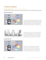
Page 18: ...ubber The vacuum will also be engaged when this button is pressed The machine is now ready to scrub This button lowers the squeegee located at the rear of the machine The vacuum will also be initiated when this button is used It will recover water with squeegee only Pressing the vacuum button a second time raises the squeegee and shuts the vacuum off There will be a slight delay before the motor s...

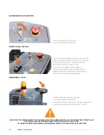
Page 19: ...or s surface Only the scrub deck is engaged while double scrubbing The squeegee is not in operation allowing solution to remain on the floor for increased cleaning solution dwell time WARNING Double scrubbing is functional in manual mode only and should only be used in a controlled environment where there is no potential for slipping and falling HORN Initiate double scrubbing by using the one touc...

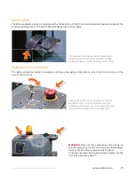
Page 20: ...abled scrubber in reverse the squeegee will raise automatically In addition the vacuum motor turns off after a short delay This prevents damaging squeegee The Brain enabled scrubber is equipped with two emergency stop buttons Press this button in an emergency Doing so engages the brake immediately and stops all scrubber function Insert momentary key into ignition and turn clockwise to start power ...

Page 21: ...ory settings DETERGENT LEVELS INDICATOR AND CONTROL WATER LEVEL INDICATOR AND CONTROL SCRUBBER PRESSURE CONTROL If any of the warning indicators outlined above appear cease operating machine and correct problem Additional detailed information about each error outlined below will appear on the Brain enabled scrubber display To regulate amount of detergent released onto floor press blue plus and min...

Page 22: ...he ROC See section on ROC for further details USER INTERFACE LCD TOUCHSCREEN The user interface LCD screen displays various menus that control a variety of functions and options of the Brain enabled scrubber including teaching route choosing route and machine settings The user interface is a touchscreen component and user may command the machine by simply touching items that appear on the menu on ...

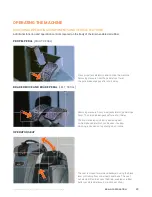
Page 23: ...l to drive the machine Removing pressure from the pedal stops travel The park brake engages after short delay Removing pressure from propel accelerator pedal stops travel The park brake engages after a short delay The Brain enabled scrubber is also equipped with a brake pedal which can be used if quicker stopping is needed or if operating on an incline The seat is moved forward and backward using ...

Page 24: ...ocation Codes In addition the following key terms and definitions must be understood to successfully operate the Brain enabled scrubber ROUTE TEACH A NEW CLEANING ROUTE This is the course your ICE RS26 robotic scrubber powered by Brain OS follows during cleaning Before your robotic scrubber powered by Brain OS can clean on its own an operator must drive the Brain enabled scrubber through each desi...

Page 25: ...nlet filter clean them if necessary 3 Check the vacuum hose for debris or blockage Check the squeegees for damage wear and for deflection adjustment 4 Check whether the pad brush is installed properly Check the brakes and steering for proper operation 5 Check that the rear squeegee and side skirts are free of tears rips and excessive wear and are picking up water properly 6 Check the water solutio...

Page 26: ...manual cleaning is to be conducted select desired cleaning settings using the scrubber depth indicator detergent level indicator and water level indicator adjustment buttons 6 The machine may now be driven manually to conduct cleaning 7 When driving the machine it is important to maintain a safe distance from the edge of ramps platforms and other objects 8 Go slow on inclines and slippery surfaces...

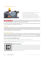
Page 27: ...d one in the rear of the machine The machine is also equipped with a brake pedal that can be used to control the machine if quicker stopping is needed or when operating on an incline Pushing this button in an emergency shuts off all manual functions To restart machine reset the emergency stop button turn off the momentary key ignition switch and then turn on the key switch WARNING Only use the eme...

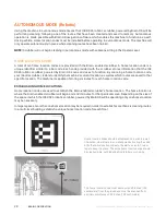
Page 28: ...ion code your robotic scrubber is able to identify the machine s current location as well as which routes are saved to that specific location The machine is capable of storing six routes for each home location code ESTABLISHING HOME LOCATIONS Home location codes are used to establish the Brain enabled scrubber s home location The home location is where the Brain enabled scrubber will begin and end...

Page 29: ...ht around the home location code 5 If the home location code is visible within the live video camera view and the Brain enabled scrubber is within the appropriate distance from the code the machine will begin scanning and state Scanning Home Location You will see a green highlight around the image of the code on the UI 6 Once the Brain enabled scrubber completes scanning the home location code a S...

Page 30: ... not scan the code if the Brain enabled scrubber is not properly positioned 3 When the Brain enabled scrubber sees the home location code it will be visible via the live video image on the user interface LCD screen and scanning animations will appear on the LCD screen A message will appear on the user interface LCD screen stating Scanning Home Location 4 Once the Brain enabled scrubber completes s...

Page 31: ...ULAR SERVICE IS NEEDED FOR THE MACHINE TO CONNECT TO THE ROC The ROC Indicator is located on the user interface LCD screen in the status bar When the ROC Indicator is illuminated orange the Brain enabled scrubber is successfully connected to the ROC Connecting the Brain enabled scrubber to the ROC allows for registering to receive SMS status alerts while your robotic scrubber is functioning autono...

Page 32: ...n tank of all fluid 8 Drain the recovery tank of all fluid clean the recovery tank and flush the drain hose empty and clean and the yellow debris strainer basket at the top of the recovery tank DRAINING THE RECOVERY TANK Each time scrubbing is completed or when refilling solution tank the recovery tank should be drained and cleaned WARNING If the recovery tank is not drained when the solution tank...

Page 33: ...olts NOTE The machine cannot operate when charging ON BOARD BATTERY CHARGER The ICE RS26 powered by Brain OS robotic scrubber has an on board charger position below the seat above the foot plate 1 Place the machine in a well ventilated area 2 Turn the machine off 3 If charging wet lead acid batteries check the fluid level before charging ON BOARD BATTERY CHARGER CONT 1 Prop the Operator seat using...

Page 34: ...surfaces being cleaned Replace when the items are worn MONTHLY MAINTENANCE 1 Clean the battery tops to prevent corrosion 2 Check for loose battery cable connections 3 Inspect and clean recovery tank cover seal Replace if damaged 4 Lubricate all grease points and pivot points with silicon spray and approved grease 5 Check machine for loose nuts and bolts 6 Check machine for leaks MOTOR MAINTENANCE ...

Page 35: ... tank check vacuum fan inlet filter clean if necessary 3 Check vacuum hose for debris or blockage Check squeegees for damage wear and for deflection adjustment 4 Check whether pad brush is installed properly 5 Check brakes and steering for proper operation 6 Check to ensure sensors are clean and not obstructed ADJUSTING SCRUBBERS AND SQUEEGEE Adjusting Scrubbers and Squeegee REAR SQUEEGEE SIDE SQU...

Page 36: ...ition For best cleaning performance the side skirt should be adjusted such that the blade flares outward slightly when the deck is lowered Check the adjustment by operating the machine and verifying that the skirt wipes water properly during turns If the side skirt is too high it will leave water during turns If the skirt is adjusted too low wiping will not be optimal and the blades will wear prem...

Page 37: ...are required to move the machine once the brake is released one person to steer and one to push Check for and clean up any residual water or liquids on the ground before performing the brake release procedure Be cautious not to slip on wet floors especially while pushing the machine Do not attempt to perform this brake release procedure if you have any health issues or physical limitations that wo...

Page 38: ... the brush out from underneath the machine The machine is now ready for placement of new brushes INSERTING NEW BRUSH Slide the new brush underneath the machine and push it upwards into the sprocket until it snaps into place The brush will still wobble from side to side even after it has been secured in place Brushes should be replaced when they begin to appear thin or covered with debris The side ...

Page 39: ...y are clean and free of smudges Clean any dirt and dust off using the microfiber cloth provided Do not apply water to the sensors OR cloth Inspect Pads Brushes Squeegees As brushes wear down the scrub deck gets lower Ensure the side squeegees are adjusted properly and raise them as the brushes wear down Replace worn brushes and pads Inspect rear squeegee for wear and flip or replace if necessary E...

Page 40: ...gate must be at least five feet wide Any u turn with the ICE RS26 robotic scrubber powered by Brain OS requires at least 10 ft for a u turn MANUAL AND AUTONOMOUS MODE When using the Brain enabled scrubber in manual mode to clean do not end operation abruptly It s best to drive the machine slightly beyond the end of the cleaning route and then inspect the floor to ensure that all water has been rem...

Page 41: ...nk is empty and that the strainer basket and filter are both clean 3 Fill water and cleaning solution tanks 4 Inspect squeegees and brushes pads for wear damage and proper installation 5 Inspect and clear any dust or debris from all sensors 6 Check and adjust machine control settings 7 Check side skirt and adjust for proper wiping In addition inspect rear squeegee function for proper water pick up...

Page 42: ...e to pair your phone each day you use the machine This is to ensure only an on site operator will receive the notifications Once you turn the machine off or if another operator connects you will no longer receive notifications Q ROBOTIC SCRUBBER GETS STUCK IN THE SAME PLACE EVERY DAY THERE IS NOTHING THERE BUT SHE ALWAYS STOPS AND ASKS FOR HELP WHAT S GOING ON A There could be an environmental fac...

Page 43: ...cator will blink continuously in conjunction with an audible alarm When a fault occurs discontinue operating the machine until the fault is eliminated Turn off the machine and resolve the fault The fault code will be eliminated when the machine is restarted If a component alert or fault occurs frequently or the fault cannot be eliminated please contact your service provider Refer to the table on t...

Page 44: ...ne If The Fault Continues Contact Service Center F6 Brush Overload Brush motor overload Turn Off The Machine Wait A Moment Restart Machine If The Fault Continues Contact Service Center F7 Propel Error Propel motor overload Turn Off The Machine Wait A Moment Restart Machine If The Fault Continues Contact Service Center F8 Recovery Tank Full Recovery tank is full Drain the recovery tank F8 Recovery ...

Page 45: ...UM MOTOR DOES NOT RUN OR RUNS SLOWLY Recovery Tank Full Drain Recovery Tank Recovery Tank Float System Dirty Clean Float System Circuit Breaker Tripped Reset Circuit Breaker Loose Connection Check Motor Wires and Connections Faulty Vacuum Switch Replace Switch Worn Vacuum Motor Brushes Replace Brushes or Pads POOR SCRUBBING PERFORMANCE Debris Caught in Scrub Brushes Remove Debris Worn Brushes or P...

Page 46: ... Clean Connections Faulty Main Contactor Replace Contactor Faulty Key Switch Replace Switch LITTLE OR NO PROPEL Low Battery Charge Charge Batteries Wheels Spin Decrease Brush Pressure Controller Overheated Allow Cool Down Period Adjust Brush if Needed Loose Connection Check Motor Wires and Connection WATER TANK READS EMPTY WHEN IT IS NOT EMPTY Water Tank Float Switch Is Damaged Repair Replace Floa...

Page 47: ...Subject to Change Brain Corporation 47 WHERE TO GET MAINTENANCE AND SUPPORT CUSTOMER SUPPORT 1 888 834 9948 servicebraincorp triadservice com If you see this error on the display please reboot the machine If the problem persists please contact support ...

Page 48: ...roBotiC sCruBBer iCe rs26 gen2 poWered By Brainos V1 1217 CONTENT SUBJECT TO CHANGE ...

Reviews: