Ice-O-Matic ICEF 155 Service Manual Download Page 23

Page 23

Page 23

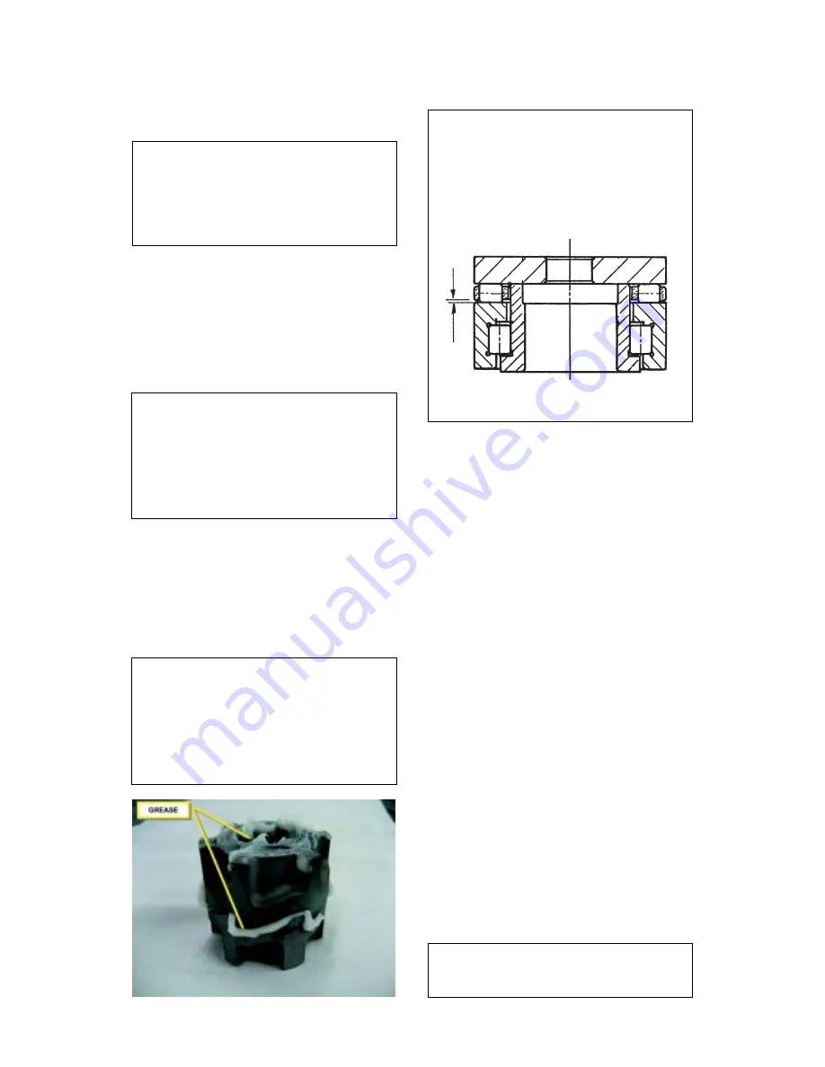
NOTE. Install the upper bearing into the ice
breaker starting by the radial portion that
must be fitted with the flat surface facing up.
Apply some lubricant (grease) on the upper
surface then install the rollers cage with the
smaller openings of the same facing up so to
leave a small gap between plastic cage and
flat surface of the botton portion of the bearing
(see drawing).

Apply some move lubricant then place the
S.S. trust washer.

J.

REPLACEMENT OF THE GEAR MOTOR
ASSY

1.

Remove the rear side and top panels.

2.

Remove the three bolts and washers

securing the gear reducer base to the unit chassis,
then remove bolts and lockwashers which attach
the bottom of the aluminium adaptor to the gear
reducer case cover.

3.

Disconnect the electrical leads from the

electromagnetic safety device located on top of
drive motor.

4.

Trace and disconnect the electric wires leads

of the drive motor. Lift and remove the entire
gear motor assembly.

5.

To install the replacement gear motor assy

follow the above steps in reverse.

K.

REPLACEMENT OF FAN MOTOR

1.

Remove front and side panels.

2.

Remove screws and yellow green ground

wire. Trace the electrical leads of fan motor and
disconnect them.

3.

Remove the bolts securing the fan motor

bracket to the cabinet base and then remove the
assembly.

4.

To install the replacement fan motor follow

the above steps in reverse.

NOTE. When installing a new fan motor
check that the fan blades do not touch any
surface and move freely.

8.

Slide off from the auger bottom the upper

half of the water seal.

NOTE. Any time the auger is removed for
replacement or inspection use extra care in
handling the water seal parts, so no dirt or
foreign matters are deposited on the surfaces
of the seal. If there is any doubt about the
effectiveness of the water seal or O ring do
not hesitate to REPLACE THEM.

9.

Unloose and remove the three bolts and

lockwashers which attach the freezer assy to the
aluminium adaptor.

10. Raise the freezer assy off the adaptor, secure
it out of the way to allow room to work. Using a
suitable lenght and size wooden dowel or stick
inserted through the top of the open freezer, tap
the lower half of the water seal and the lower
bearing out the bottom of the freezer.

NOTE. It is good practice to replace the
water seal assy and both the top and the
bottom bearings any time the auger is
removed.
To facilitate this, SCOTSMAN EUROPE
Service makes available a service Kit
P/N 001028.07 which includes besides the
above mentioned parts, the ice breaker O ring
and a can of food grade waterproof grease.

11. Reach through the adaptor and remove the
coupling parts.

12. Check both the coupling halves for chipping
and wear and do not hesitate to replace them.

13. To install the ratched coupling, the water
seal, the bearings and auger follow previous
steps in reverse.

NOTE. It is very important to provide correct/
proper lubrication of the inside bore of the
upper semi-coupling as well as to the external
surfaces of the teeth as shown on the here
below photo.
The correct lubrication allows the upper semi-
coupling to move it down, by the load of the
upper spring, in case of any rising up during
its rotation.

Summary of Contents for ICEF 155

Page 1: ...Page 1 Page 1 SERVICE MANUAL ICE UNDERCOUNTER SERIES CUBER MODEL ICEF 155 Rev 07 2014...

Page 2: ...rain connections Final check list Installation practice OPERATING INSTRUCTIONS Start up Operational checks PRINCIPLE OF OPERATION How it works Water circuit Refrigerant circuit Mechanical system Opera...

Page 3: ...ak performance levels periodic maintenance checks must be carried out as indicated on page 29 of this manual Important operating requirements MIN MAX Air temperature 10 C 50 F 40 C 100 F Water tempera...

Page 4: ...NS Model Cond unit Finish Comp HP Ice bin cap Water req lt 24 HR ICEF 155 MACHINE SPECIFICATIONS Dimensions HEIGHT less legs 794 mm HEIGHT with legs 929 mm WIDTH 529 mm DEPTH 621 mm WEIGHT 51 Kg 230 5...

Page 5: ...nting pads 8 Use clean damp cloth to wipe the surfaces inside the storage bin and the outside of the cabinet 9 See data plate on the rear side of the unit and check that local main voltage corresponds...

Page 6: ...ter or conditioner WATERSUPPLY WATERCOOLEDMODELS The water cooled versions of Ice Makers require two separate inlet water supplies one for the water making the flaker ice and the other for the water c...

Page 7: ...Have the bin liner and cabinet been wiped clean 10 Has the owner user been given the User Manualandbeeninstructedontheimportanceof periodic maintenance checks G INSTALLATION PRACTICE 1 Hand shut off v...

Page 8: ...hardastheevaporating temperature has not yet reached the correct operating value It is necessary to allow the ice just made to cure itself and wait for about ten minutes for the evaporating tem peratu...

Page 9: ...SER TEMP EVAPORATOR TEMP ICE LEVEL CONTROL TRANSF T 40 50 C DATA PROCESSOR L N 11 10 9 1 2 7 8 6 5 4 3 13 12 FIG 3 2 1 L N COMPRESSOR 9 10 11 12 13 3 4 5 6 7 8 CONTACTOR COIL GEAR MOTOR FAN MOTOR ELEC...

Page 10: ...PERATION CHECKS UPON THE UNIT START UP D Removefrontservicepanelandifnecessary install the refrigerant service gauges on the corresponding Service valves to check both the HI and LO refrigerant pressu...

Page 11: ...of the flaker operations and the glowing of the YELLOW LED of shortage of water even though that water is indeed in the reservoir After this open the water supply line shutoff valve to fill up again t...

Page 12: ...ss of the two optical eyes are covered by a thin lay of scale To do it just follow the following procedure With unit OFF push and old the Reset Button of the PC Board Give power to the machine through...

Page 13: ...the ice level raises to interrupt the light beam running between the two infrared Leds the unit stops after six seconds with the simulteneous glowingofthe YELLOWLEDsignallingthe Full Bin situation NO...

Page 14: ...unit trips OFF again in alarm for 3 times in 3 hours the machine SHUTS OFF DEFINITIVELY After having eliminated the source of the excessive con densertemperature torestarttheicemachine it is necessary...

Page 15: ...4 5 6 7 8 CONTACTOR COIL GEAR MOTOR FAN MOTOR ELECTRONIC CARD RELAYS TRIAC RESET S E N S O R S WATER LEVEL GEAR MOTOR ROTATION CONDENSER TEMP EVAPORATOR TEMP ICE LEVEL CONTROL TRANSF DATA PROCESSOR L...

Page 16: ...em always check the type of refrigerant and quantity as specified on the individual ice machine dataplate Therefrigerantchargesindicatedarerelatives to averages operating conditions OPERATING PRESSURE...

Page 17: ...tage to the P C BOARD In case the condenser temperature sensor detects a temperature at the condenser lower than 1 C 33 F that signify that the ambient temperature is at the same value therefore it is...

Page 18: ...LED F P C BOARD Data processor The P C BOARD fitted in its plastic box located in the front of the unit consists of two separated printed circuits one at high and the other at low voltage and protecte...

Page 19: ...low to maintain a constant water level in the reservoir level that corresponds to the one in thefreezingcylindertoensurepropericeformation and fluidity On the inner side of the reservoir cover are fit...

Page 20: ...erefrigerant vaporcausingitstemperaturetoriseandbecome high pressure hot vapor which is then released through the discharge valve NOTE Itisveryimportanttomakesureofthe correct fitting of the cover on...

Page 21: ...ezertotheaccumulator to gain access to the sensor probe well and be able to pull out from this well the sensor probe 3 Trace the condenser sensor terminal plug blue on the left side of the control box...

Page 22: ...he machine stops with all LEDs blinking H REPLACEMENT OF THE ICE SPOUT 1 Remove the top panel 2 Slacken and remove the two metal straps that hold tight the polystyre insulations against the freezer up...

Page 23: ...e off from the auger bottom the upper half of the water seal NOTE Any time the auger is removed for replacement or inspection use extra care in handling the water seal parts so no dirt or foreignmatte...

Page 24: ...It is imperative to install a replace ment drier whenever the sealed refrigeration system is open Do not replace the drier until all other repairs or replacements have been completed 8 To install the...

Page 25: ...Page 25 Page 25 WIRING DIAGRAM AIR AND WATER COOLED 230 50 60 1...

Page 26: ...Page 26 Page 26...

Page 27: ...freezer for scores Replace whatever worn or damaged No rotation of gear motor Check for power to drive motor 16 A fuses Check for stator winding Gear motor starts and stop Check for correct operation...

Page 28: ...leaking Tighten screws holding the spout Excessive noise or chattering Mineral or scale deposit on auger Remove and manually polish auger and inner freezer walls and inner walls of freezer barrel usin...

Page 29: ...t temperature sensor 8 Check for water leaks and tighten drain line connections Pour water down bin drain line to be sure that drain line is open and clear 9 Check the ice level control sensor to test...

Page 30: ...heoverflow NOTE The ice made with the cleaning solution is slushy and coloured also it may tendtoloosefluiditycreatingsomeresistence in being elevated and extruded this situation canbeheardbythecreack...

Reviews: