Ice-O-Matic GEMD270A2 Installation And Service Manual Download Page 10

OPERATING INSTRUCTIONS

START UP

After having correctly installed the ice maker and
completed the plumbing and electrical connec-
tions, perform the following “Start-up” procedure.

A.

Open the water supply line shutoff valve and

give power by moving the main switch, on the
power supply line, to the ON position.
The GREEN LED will glow to signal that unit is
under power.

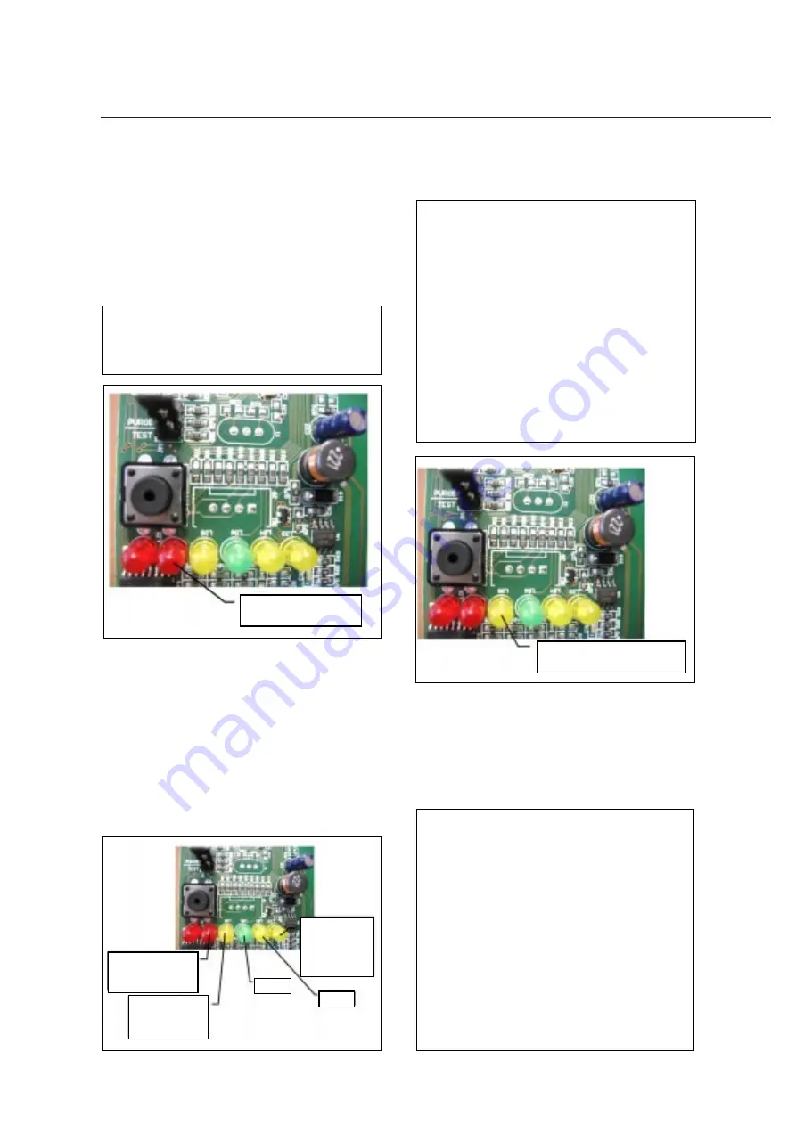
NOTE. Every time the unit is put under power,
after being kept for sometime in shut-off
conditions (electrically disconnected) the  2nd
RED LED will blink for 3 minutes (Fig.1).

B.

Elapsed the 3 minutes - stand by period - the

unit starts operating with the activation in
sequence of the following assemblies:

GEAR MOTOR

COMPRESSOR

FAN MOTOR  kept under control by the
condenser temperature sensor which has its
probe within the condenser fins
with the switching off of the 2nd RED LED
(Fig. 2).

C.

2 or 3 minutes after the compressor start up,

observe that flaker ice begins dropping off the ice
spout to fall into the storage bin.

NOTE. If, after ten minutes from the

compressor start-up, the evaporating tem-
perature has not dropped down to a value
lower than -1

°

C (30

°

F) the evaporating tem-

perature sensor detects such an abnormal


situation and stops consequently the unit
operation.
In this circustance, the 3rd warning YELLOW


LED will blink (Fig.3).
After having diagnosed and eliminated the


cause of the poor evaporating temperature


(insufficient refrigerant in the system or
inoperative compressor or evaporator sensor)


it is 

necessary to push the RE-SET BUTTON


or  De-

engerize and re-engerize unit

.


The unit, before 

resuming the total operation,


will go through the 

usual 3 minutes STAND-BY period.

OPERATION CHECKS UPON THE UNIT
START UP

D.

Remove service panels and if necessary

install the refrigerant service gauges on the
corresponding Service valves to check both the
HI and LO refrigerant pressures.

NOTE. The condenser temperature sensor,
which is located within the condenser fins,
keeps the head (condensing) pressure
between two preset valves.
In case of condenser clogging such to prevent
the proper flow of the cooling air or, in case
the fan motor is out of operation, the
condenser temperature rises and when it
reaches 70

°

C (160

°

F) the condenser tempe-

rature sensor shuts-off the ice maker with the
consequent light-up of the 2nd RED
WARNING LIGHT
 (Fig.4).
After having diagnosed the reason of the
temperature rise and removed its cause, it is
necessary to proceed as per the previous
“NOTE” to start up again the operation of the
ice maker.

FIG. 1

BLINKING - FLASHING

3 MINUTES DELAY TIME AT START UP

BLINKING-FLASHING SLOW

INFRARED BEAM CUTTED

WITH MACHINE IN OPERATION

STEADY

MACHINE OFF AT BIN FULL
BLINKING-FLASHING FAST

INFRARED BEAM ON AFTER

THE TRIPPING OFF AT BIN FULL

NO WATER

POWER ON

BLINKING-FLASHING

3 MINUTES DELAY TIME AT START UP

STEADY

TOO HI CONDENSING TEMPERATURE

BLINKING-FLASHING

TOO HI EVAPORATING TEMP.

AFTER 10 MIN. FROM START UP

STEADY

WRONG-NO-SLOW ROTATION

GEAR MOTOR

FIG. 2

FIG. 3

BLINKING - FLASHING

TOO HI EVAPORATING TEMP. AFTER 10 MIN.

FROM START UP

GEMD270A

Page


8

Summary of Contents for GEMD270A2

Page 1: ...GEMD270A2 PEARL ICE ICE WATER DISPENSER MODELS GEMD270A2 Installation and Service Manual Ice O Matic 11100 E 45 th Ave Part Number 9081407 01 Revision 03 23 21 Denver Colorado 80239 1 866 PURE ICE...

Page 2: ...SERVICE PARTS MANUAL 22 INCH WIDE ICE SERIES CUBERS MODEL ICE0320 ICE0520 Includes 50Hz Units ICE O Matic 11100 East 45th Ave Denver Colorado 80239 Part Number 9081297 01 PD04 02 Rev1 05...

Page 3: ...ONNECTIONS Page 5 WATER SUPPLY AND DRAIN CONNECTIONS Page 6 FINAL CHECK LIST Page 7 OPERATING INSTRUCTIONS Page 8 INITIAL START UP CONTINUED Page 9 SETTING THE DISPENSING SELECTOR Page 11 PRINCIPLE OF...

Page 4: ...S GEMD270A Page 2 Model Cond unit Cabinet Size Finish Comp HP Ice bin cap GEMD270A Air 34 13 32 high x 15 9 32 wide x 26 7 64 deep S Steel 3 8 12 lb Basic electrical Amps Watts Amps fuse 115 60 1 6 55...

Page 5: ...CABINET DIAGRAMS GEMD270A Page 3...

Page 6: ...including Model and Serial Number taken from the data plate Forward the completed self addressed registration card to Ice O Matic factory LOCATION AND LEVELING WARNING This Ice Dispenser is designed...

Page 7: ...e machine is connected to its own circuit and individually fused see data plate for fuse size Not Connected to a G F I outlet The maximum allowable voltage variation should not exceed 10 and 10 of the...

Page 8: ...ar WATER SUPPLY Connect to the male water inlet fitting using the supplied fitting to the cold water supply line A shut off valve should be installed in an accessible position between the water supply...

Page 9: ...en checked to ensure a flowing water pressure of at least 20 psi 7 Check all refrigerant lines and conduit lines to guard against vibrations and possible failure 8 Has the unit been sealed to the coun...

Page 10: ...the system or inoperativecompressororevaporatorsensor itis necessarytopushtheRE SETBUTTON or De engerizeandre engerizeunit Theunit before resumingthetotaloperation willgothroughthe usual3minutesSTAND...

Page 11: ...compressor F Check for the correct operation of the electronic eye for the ice bin level control by placing one hand between the sensing eyes located in the ice spout to interrupt the light beam This...

Page 12: ...eneous glowing of the YELLOW LED signalling the Full Bin situation NOTE The interruption of the light beam between the two light sensors is immediately signalled by the blinking of the 6th YELLOW LED...

Page 13: ...d coupling a worn shaft or auger placed on its vertical axis within the freezing cylinder The gear motor is made of a single phase electric motor with a permanent capacitor This motor is directly fitt...

Page 14: ...40 psig Suction pressure 1 bar 14 psig REFRIGERANT CHARGE R 134 A 370 gr NOTE Beforechargingtherefrigerantsystem always check the type of refrigerant and quantity as specified on the individual ice ma...

Page 15: ...MANUAL RESET see NOTE The condenser temperature sensor probe located within the condenser fins detects the condenser temperature variations and signals them by supplying current at low voltage to the...

Page 16: ...e towards a rectangular opening located in the bottom of the storage bin Elapsed the dispensing time 5 10 or 15 seconds according to the setting or after removing the glass carafe the infrared resume...

Page 17: ...owing instructions Switch OFF the machine Push and hold the PC Board push button Switch ON the machine keepiung pushed the PC Board push button till all LEDs are ON Release the push button ALL STEADY...

Page 18: ...earings permanently lubricated The gear case contains a train of three spur gears the first one of which is in fiber to limit the noise level All the three gears are encased in case bearings and are c...

Page 19: ...ing the proper membrane button b Place a glass or a carafe in front of the two Optical Dispensing Devices c The dispensing drive motor and or the water solenoid valve starts Ice and or water is discha...

Page 20: ...ps Check for correct operation of drive after a while motor magnetic sensor Check for correct magnetic capacity of magnetic cylinder Compressor cycles intermittently Low voltage Check circuit for over...

Page 21: ...st float valve setting screw Excessive noise or chattering Mineral or scale deposit on auger Remove and manually polish auger and inner freezer walls and inner walls of freezer barrel using emery pape...

Page 22: ...p of a bit of ice machine cleaner plain 7 With the ice machine and fan motor OFF clean condenser using vacuum cleaner whiskbroom or non metallic brush taking care to do not damage the condenser temper...

Page 23: ...ored It may also loose fluidity creating some resistance in being elevated and extruded this situation can be heard by the creaking noise made by the ice If this should occur it is recommended that yo...

Page 24: ...n 11 Remove nut holding bin to chassis 12 Pull bin out of machine 13 Remove screws holding air deflector to chassis and pull deflector out of the unit 14 Remove screws holding reservoir to bulkhead pa...

Page 25: ...ace large washers over coupling and small washer under bottom of bearing Insert bolt through large washers coupling and bearing Run one nut into bearing to center the bolt Add small washer and nuit Ti...

Page 26: ...e thrust bearing and place it on top of the roller bearing The inner race of the roller bearing must project through the center of the flat thrust bearing 9 Install the flat washer provided with the n...

Page 27: ...ring and bottom seal Rotating Half 1 Remove old rotating half from the auger Clean the mounting area 2 Place a bead of food grade sealant onto the shoulder of the auger where the rotating half of the...

Reviews: