ICE Series
Refrigeration System
Page E4
Thermostatic Expansion Valve (Continued)
A dual evaporator machine will have one TXV for each evaporator. If one TXV sticks open and the
other is operating normally, the suction pressure will be higher than normal and both evaporators
will build thick ice. It is recommended that both valves be replace if one sticks open.
If one TXV sticks closed and one is operating normally, the suction pressure will be normal or low
but the evaporator with the defective valve will be starved (thick ice at the bottom and thin ice at
the top).
Evaporator
As water is circulated over the front of the evaporator, liquid refrigerant is circulated through the
tubing attached to the back of the evaporator. As the liquid refrigerant in the tubing vaporizes, it
absorbs heat from the water causing the water to freeze. The evaporator should be completely
flooded throughout most of the freeze cycle. A flooded evaporator will build ice evenly across the
evaporator. A starved evaporator will have uneven ice formation. Most problems with ice
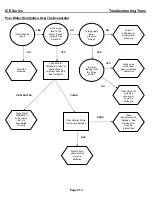
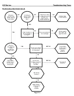
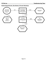
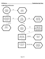
formation or harvesting are not related to a defective evaporator, use the Troubleshooting Trees in
section C for additional help.
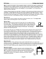
Refrigerant enters the evaporator through the bottom tube and exits through the top tube. On
models ICE800, 1000, 1800 and 2100 the refrigerant line at the TXV outlet splits into two feeder
tubes. This split occurs at the distributor, which is a fitting that is soldered to the TXV. One feeder
tube from the distributor feeds the top of the evaporator; the other tube feeds the bottom of the
evaporator. The evaporator tubes run parallel, in opposite directions, along the back of the
evaporator creating a dual pass.
If the evaporator is flooded but not building ice evenly, it is possible the evaporator has coil
separation. Evaporator coil separation is the separation of the refrigerant tubing from the back of
the evaporator plate. This is very rare but occasionally occurs.
To confirm coil separation, remove and check the back of the evaporator. If the coil is separated,
the evaporator must be replaced. If the outlet(s) of the evaporator is not frosted, the problem is not
with coil separation (Refer to the troubleshooting trees, section C).
In
In
Out
In
Out
Out
Summary of Contents for 16
Page 19: ...ICE Series General Information Page A17 Electrical and Plumbing Requirements ICE1506 Remote ...
Page 86: ...ICE Series Wiring Diagram Page G1 ICEU150 200 205 206 Air and Water Wiring Diagram ...
Page 87: ...ICE Series Wiring Diagram Page G2 ICEU150 200 205 206 Air and Water Wiring Schematic ...
Page 88: ...ICE Series Wiring Diagram Page G3 ICEU150 220 225 226 Air and Water Wiring Diagram ...
Page 89: ...ICE Series Wiring Diagram Page G4 ICEU150 220 225 226 Air and Water Wiring Schematic ...
Page 90: ...ICE Series Wiring Diagram Page G5 ICE0250 Air and Water Wiring Diagram ...
Page 91: ...ICE Series Wiring Diagram Page G6 ICE0250 Air and Water Wiring Schematic ...
Page 92: ...ICE Series Wiring Diagram Page G7 ICE0400 Air and Water Wiring Diagram ...
Page 93: ...ICE Series Wiring Diagram Page G8 ICE0400 Air and Water Wiring Schematic ...
Page 94: ...ICE Series Wiring Diagram Page G9 ICE0405 0406 Air and Water Wiring Diagram ...
Page 95: ...ICE Series Wiring Diagram Page G10 ICE0405 0406 Air and Water Wiring Schematic ...
Page 96: ...ICE Series Wiring Diagram Page G11 ICE0500 Air and Water Wiring Diagram ...
Page 97: ...ICE Series Wiring Diagram Page G12 ICE0500 Air and Water Wiring Schematic ...
Page 98: ...ICE Series Wiring Diagram Page G13 ICE0500 Remote Wiring Diagram ...
Page 99: ...ICE Series Wiring Diagram Page G14 ICE0500 Remote Wiring Schematic ...
Page 102: ...ICE Series Wiring Diagram Page G17 ICE0605 0606 0805 0806 1005 1006 Remote Wiring Diagram ...
Page 103: ...ICE Series Wiring Diagram Page G18 ICE0605 0606 0805 0806 1005 1006 Remote Wiring Schematic ...
Page 104: ...ICE Series Wiring Diagram Page G19 ICE1007 Air and Water Wiring Diagram ...
Page 105: ...ICE Series Wiring Diagram Page G20 ICE1007 Air and Water Wiring Schematic ...
Page 106: ...ICE Series Wiring Diagram Page G21 ICE1007 Remote Wiring Diagram ...
Page 107: ...ICE Series Wiring Diagram Page G22 ICE1007 Remote Wiring Schematic ...
Page 108: ...ICE Series Wiring Diagram Page G23 ICE1405 1406 1806 2005 2106 Air and Water Wiring Diagram ...
Page 109: ...ICE Series Wiring Diagram Page G24 ICE1405 1406 1806 2005 2106 Air and Water Wiring Schematic ...
Page 110: ...ICE Series Wiring Diagram Page G25 ICE1405 1406 1806 2005 2106 Remote Wiring Diagram ...
Page 111: ...ICE Series Wiring Diagram Page G26 ICE1405 1406 1806 2005 2106 Remote Wiring Schematic ...
Page 112: ...ICE Series Wiring Diagram Page G27 ICE1407 1807 2107 Air and Water Wiring Diagram ...
Page 113: ...ICE Series Wiring Diagram Page G28 ICE1407 1807 2107 Air and Water Wiring Schematic ...
Page 114: ...ICE Series Wiring Diagram Page G29 ICE1407 1807 2107 Remote Wiring Diagram ...
Page 115: ...ICE Series Wiring Diagram Page G30 ICE1407 1807 2107 Remote Wiring Schematic ...
Page 116: ...ICE Series Wiring Diagram Page G31 ICE1606 Remote Wiring Diagram ...
Page 117: ...ICE Series Wiring Diagram Page G32 ICE1606 Remote Wiring Schematic ...
Page 118: ...ICE Series Wiring Diagram Page G33 ICE0320 Air and Water Wiring Diagram ...
Page 119: ...ICE Series Wiring Diagram Page G34 ICE0320 Air and Water Wiring Schematic ...
Page 120: ...ICE Series Wiring Diagram Page G35 ICE0520 Air and Water Wiring Diagram ...
Page 121: ...ICE Series Wiring Diagram Page G36 ICE0520 Air and Water Wiring Schematic ...
Page 122: ...ICE Series Wiring Diagram Page G37 ICE0325 0525 Air and Water Wiring Diagram ...
Page 123: ...ICE Series Wiring Diagram Page G38 ICE0325 0525 Air and Water Wiring Schematic ...
Page 124: ...ICE Series Wiring Diagram Page G39 ICE0305 Air and Water Wiring Diagram ...
Page 125: ...ICE Series Wiring Diagram Page G40 ICE0305 Air and Water Wiring Schematic ...
Page 126: ...ICE Series Wiring Diagram Page G41 ICE1506 Remote ...
Page 127: ...ICE Series Wiring Diagram Page G42 ICE1506 Remote ...
Page 128: ...ICE Series Wiring Diagram Page G43 ICEU300 Air and Water ...
Page 129: ...ICE Series Wiring Diagram ICEU300 Air and Water Page G44 ...
Page 130: ...ICE Series Wiring Diagram Page G45 ICEU305 Air and Water ...
Page 131: ...ICE Series Wiring Diagram Page G46 ICEU305 Air and Water ...
Page 132: ...ICE Series Wiring Diagram Page G47 ICE0500 Remote Wiring Diagram R3 ...
Page 133: ...ICE Series Wiring Diagram Page G48 ICE0500 Remote Wiring Schematic R3 ...
Page 134: ...ICE Series Wiring Diagram ICE0605 0606 0806 1006 Remote Wiring Diagram R3 Page G49 ...
Page 135: ...ICE Series Wiring Diagram Page G50 ICE0605 0606 0806 1006 Remote Wiring Schematic R3 ...
Page 136: ...ICE Series Wiring Diagram Page G51 ICE1007 Remote Wiring Diagram R3 ...
Page 137: ...ICE Series Wiring Diagram Page G52 ICE1007 Remote Wiring Schematic R3 ...
Page 146: ...ICE Series Wiring Diagram ICE0500 Air3 and Water3 Wiring Diagram Page G61 ...
Page 147: ...ICE Series Wiring Diagram Page G62 ICE0500 Air3 and Water3 Wiring Schematic ...
Page 148: ...ICE Series Wiring Diagram Page G63 ICE0500 Remote4 Wiring Diagram ...
Page 149: ...ICE Series Wiring Diagram Page G64 ICE0500 Remote4 Wiring Schematic ...
Page 151: ...ICE Series Wiring Diagram Page G66 ICE0606 Air3 and Water3 ICE0605 Air3 and Water3 ...
Page 152: ...ICE Series Wiring Diagram ICE0606 Remote4 and ICE0605 Remote4 Wiring Diagram Page G67 ...
Page 153: ...ICE Series Wiring Diagram Page G68 ICE0606 Remote4 and ICE0605 Remote4 Wiring Schematic ...
Page 154: ...ICE Series Wiring Diagram Page G68 ICE0606 Remote4 and ICE0605 Remote4 Wiring Schematic ...
Page 155: ...ICE Series Wiring Diagram ICE1405 6A3 W3 ICE1806W3 and ICE2106W3 Wiring Diagram Page G69 ...
Page 156: ...ICE Series Wiring Diagram Page G70 ICE1405 6A3 W3 ICE1806W3 and ICE2106W3 Wiring Schematic ...
Page 157: ...ICE Series Wiring Diagram ICE1407A3 W3 ICE1807W3 and ICE2107W3 Wiring Diagram Page G71 ...
Page 158: ...ICE Series Wiring Diagram Page G72 ICE1407A3 W3 ICE1807W3 and ICE2107W3 Wiring Schematic ...
Page 159: ...ICE Series Wiring Diagram Page G73 ICE1405 6R3 ICE1806R3 and ICE2106R3 Wiring Diagram ...
Page 160: ...ICE Series Wiring Diagram Page G74 ICE1405 6R3 ICE1806R3 and ICE2106R3 Wiring Schematic ...
Page 161: ...ICE Series Wiring Diagram Page G75 ICE1407R3 ICE1807R3 and ICE2107R3 Wiring Diagram ...
Page 162: ...ICE Series Wiring Diagram Page G76 ICE1407R3 ICE1807R3 and ICE2107R3 Wiring Schematic ...
Page 163: ...ICE Series Wiring Diagram Page G77 ICE1506R3 Wiring Diagram ...
Page 164: ...ICE Series Wiring Diagram Page G78 ICE1506R3 Wiring Schematic ...

