ICE Series
Electrical System
Page F7
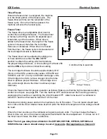
Probe Tip and Swivel
The probe tip is attached to the clutch and makes contact with the back of the ice slab during
harvest. The swivel allows the probe tip to pivot as the clutch turns so that the probe is pushed
straight through the evaporator probe guide.
The tip of the probe should be flush with the back of the evaporator or recessed up the 1/16 of an
inch (.16cm). The probe tip must not extend into the freezing area of the evaporator during freeze.
(Note: Units manufactured after June 2004 utilize a non adjustable probe.)
The length of the probe is adjustable by loosening the locknut and adjusting the probe in or out of
the swivel. Once the probe has been adjusted to the proper length, tighten the locknut. If the
probe tip binds during operation it may cause the clutch to slip unnecessarily. This may occur if
the harvest motor mounting bracket is not aligned properly or if the probe tip has excessive mineral
deposits on it. Remove and clean the probe if necessary.
To check the probe tip for binding, remove the shoulder bolt holding the swivel to the clutch and
simulate the movement of the swivel and probe by moving the swivel in a circular motion around
the outer portion of the clutch. The swivel should also move freely. If any resistance is felt the
bracket should be adjusted by loosening the bracket mounting screws and repositioning the
bracket until the probe moves freely.
Cam Switch Operation-Single Evaporator Machines
The actuator arm of the cam switch rides on the edge of the clutch assembly and is actuated by
the high and low portion of the cam. When the machine is in the freeze cycle the actuator arm of
the cam switch is in the low part of the cam. During freeze, power is supplied to the water pump
and relay 2, through the normally closed contacts of the cam switch. When the machine enters
harvest, power is supplied to the water pump and purge valve through the normally closed
contacts of the cam switch and through the normally open contacts of relay 1 (closed during
harvest). The water pump, purge valve and relay 1 remain energized until the cam switch is lifted
on to the high part of the cam. Relay 2 will also de-energize at this time allowing the machine to
shut off if the bin switch opens. Undercounter machines manufactured after July of 2004 will have
the water pump run continually until the machine shuts down.
Cam Switch Operation-Dual Evaporator Machines (Prior to January 2008)
Once the freeze timer has counted out, power is sent to: (A) harvest motor 1 and relay coil 1
through the normally closed contacts of cam switch 1, (B) to harvest motor 2 and relay coil 2
through the normally closed contacts of cam switch 2.
This
4-second
delay will allow the harvest motors to rotate and allow the cam switches to switch to
the normally open position before the low-pressure control opens during hot gas. The cam
switches are now in the normally open position and will continue to energize the harvest motors
and relays until the cam rotates and the switch returns to the normally closed position.
The bin switches are bypassed to allow the cam switch to return to the normally closed position,
prior to the machine shutting down if the curtain is open. Each harvest assist motor will only make
one revolution prior to shutting down on full bin or advancing to the next freeze cycle.
Both hot gas valves and the water purge valve remain energized until both harvest assist motors
complete one revolution. The water pump is energized throughout the harvest cycle. The unit will
shut down if the curtains are open during the freeze cycle.
Summary of Contents for 16
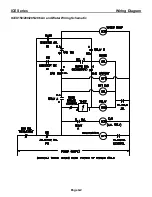
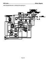
Page 19: ...ICE Series General Information Page A17 Electrical and Plumbing Requirements ICE1506 Remote ...
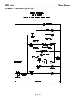
Page 86: ...ICE Series Wiring Diagram Page G1 ICEU150 200 205 206 Air and Water Wiring Diagram ...
Page 87: ...ICE Series Wiring Diagram Page G2 ICEU150 200 205 206 Air and Water Wiring Schematic ...
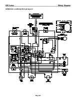
Page 88: ...ICE Series Wiring Diagram Page G3 ICEU150 220 225 226 Air and Water Wiring Diagram ...
Page 89: ...ICE Series Wiring Diagram Page G4 ICEU150 220 225 226 Air and Water Wiring Schematic ...
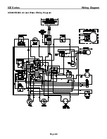
Page 90: ...ICE Series Wiring Diagram Page G5 ICE0250 Air and Water Wiring Diagram ...
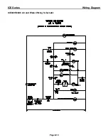
Page 91: ...ICE Series Wiring Diagram Page G6 ICE0250 Air and Water Wiring Schematic ...
Page 92: ...ICE Series Wiring Diagram Page G7 ICE0400 Air and Water Wiring Diagram ...
Page 93: ...ICE Series Wiring Diagram Page G8 ICE0400 Air and Water Wiring Schematic ...
Page 94: ...ICE Series Wiring Diagram Page G9 ICE0405 0406 Air and Water Wiring Diagram ...
Page 95: ...ICE Series Wiring Diagram Page G10 ICE0405 0406 Air and Water Wiring Schematic ...
Page 96: ...ICE Series Wiring Diagram Page G11 ICE0500 Air and Water Wiring Diagram ...
Page 97: ...ICE Series Wiring Diagram Page G12 ICE0500 Air and Water Wiring Schematic ...
Page 98: ...ICE Series Wiring Diagram Page G13 ICE0500 Remote Wiring Diagram ...
Page 99: ...ICE Series Wiring Diagram Page G14 ICE0500 Remote Wiring Schematic ...
Page 102: ...ICE Series Wiring Diagram Page G17 ICE0605 0606 0805 0806 1005 1006 Remote Wiring Diagram ...
Page 103: ...ICE Series Wiring Diagram Page G18 ICE0605 0606 0805 0806 1005 1006 Remote Wiring Schematic ...
Page 104: ...ICE Series Wiring Diagram Page G19 ICE1007 Air and Water Wiring Diagram ...
Page 105: ...ICE Series Wiring Diagram Page G20 ICE1007 Air and Water Wiring Schematic ...
Page 106: ...ICE Series Wiring Diagram Page G21 ICE1007 Remote Wiring Diagram ...
Page 107: ...ICE Series Wiring Diagram Page G22 ICE1007 Remote Wiring Schematic ...
Page 108: ...ICE Series Wiring Diagram Page G23 ICE1405 1406 1806 2005 2106 Air and Water Wiring Diagram ...
Page 109: ...ICE Series Wiring Diagram Page G24 ICE1405 1406 1806 2005 2106 Air and Water Wiring Schematic ...
Page 110: ...ICE Series Wiring Diagram Page G25 ICE1405 1406 1806 2005 2106 Remote Wiring Diagram ...
Page 111: ...ICE Series Wiring Diagram Page G26 ICE1405 1406 1806 2005 2106 Remote Wiring Schematic ...
Page 112: ...ICE Series Wiring Diagram Page G27 ICE1407 1807 2107 Air and Water Wiring Diagram ...
Page 113: ...ICE Series Wiring Diagram Page G28 ICE1407 1807 2107 Air and Water Wiring Schematic ...
Page 114: ...ICE Series Wiring Diagram Page G29 ICE1407 1807 2107 Remote Wiring Diagram ...
Page 115: ...ICE Series Wiring Diagram Page G30 ICE1407 1807 2107 Remote Wiring Schematic ...
Page 116: ...ICE Series Wiring Diagram Page G31 ICE1606 Remote Wiring Diagram ...
Page 117: ...ICE Series Wiring Diagram Page G32 ICE1606 Remote Wiring Schematic ...
Page 118: ...ICE Series Wiring Diagram Page G33 ICE0320 Air and Water Wiring Diagram ...
Page 119: ...ICE Series Wiring Diagram Page G34 ICE0320 Air and Water Wiring Schematic ...
Page 120: ...ICE Series Wiring Diagram Page G35 ICE0520 Air and Water Wiring Diagram ...
Page 121: ...ICE Series Wiring Diagram Page G36 ICE0520 Air and Water Wiring Schematic ...
Page 122: ...ICE Series Wiring Diagram Page G37 ICE0325 0525 Air and Water Wiring Diagram ...
Page 123: ...ICE Series Wiring Diagram Page G38 ICE0325 0525 Air and Water Wiring Schematic ...
Page 124: ...ICE Series Wiring Diagram Page G39 ICE0305 Air and Water Wiring Diagram ...
Page 125: ...ICE Series Wiring Diagram Page G40 ICE0305 Air and Water Wiring Schematic ...
Page 126: ...ICE Series Wiring Diagram Page G41 ICE1506 Remote ...
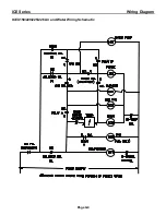
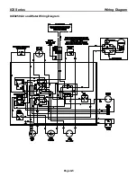
Page 127: ...ICE Series Wiring Diagram Page G42 ICE1506 Remote ...
Page 128: ...ICE Series Wiring Diagram Page G43 ICEU300 Air and Water ...
Page 129: ...ICE Series Wiring Diagram ICEU300 Air and Water Page G44 ...
Page 130: ...ICE Series Wiring Diagram Page G45 ICEU305 Air and Water ...
Page 131: ...ICE Series Wiring Diagram Page G46 ICEU305 Air and Water ...
Page 132: ...ICE Series Wiring Diagram Page G47 ICE0500 Remote Wiring Diagram R3 ...
Page 133: ...ICE Series Wiring Diagram Page G48 ICE0500 Remote Wiring Schematic R3 ...
Page 134: ...ICE Series Wiring Diagram ICE0605 0606 0806 1006 Remote Wiring Diagram R3 Page G49 ...
Page 135: ...ICE Series Wiring Diagram Page G50 ICE0605 0606 0806 1006 Remote Wiring Schematic R3 ...
Page 136: ...ICE Series Wiring Diagram Page G51 ICE1007 Remote Wiring Diagram R3 ...
Page 137: ...ICE Series Wiring Diagram Page G52 ICE1007 Remote Wiring Schematic R3 ...
Page 146: ...ICE Series Wiring Diagram ICE0500 Air3 and Water3 Wiring Diagram Page G61 ...
Page 147: ...ICE Series Wiring Diagram Page G62 ICE0500 Air3 and Water3 Wiring Schematic ...
Page 148: ...ICE Series Wiring Diagram Page G63 ICE0500 Remote4 Wiring Diagram ...
Page 149: ...ICE Series Wiring Diagram Page G64 ICE0500 Remote4 Wiring Schematic ...
Page 151: ...ICE Series Wiring Diagram Page G66 ICE0606 Air3 and Water3 ICE0605 Air3 and Water3 ...
Page 152: ...ICE Series Wiring Diagram ICE0606 Remote4 and ICE0605 Remote4 Wiring Diagram Page G67 ...
Page 153: ...ICE Series Wiring Diagram Page G68 ICE0606 Remote4 and ICE0605 Remote4 Wiring Schematic ...
Page 154: ...ICE Series Wiring Diagram Page G68 ICE0606 Remote4 and ICE0605 Remote4 Wiring Schematic ...
Page 155: ...ICE Series Wiring Diagram ICE1405 6A3 W3 ICE1806W3 and ICE2106W3 Wiring Diagram Page G69 ...
Page 156: ...ICE Series Wiring Diagram Page G70 ICE1405 6A3 W3 ICE1806W3 and ICE2106W3 Wiring Schematic ...
Page 157: ...ICE Series Wiring Diagram ICE1407A3 W3 ICE1807W3 and ICE2107W3 Wiring Diagram Page G71 ...
Page 158: ...ICE Series Wiring Diagram Page G72 ICE1407A3 W3 ICE1807W3 and ICE2107W3 Wiring Schematic ...
Page 159: ...ICE Series Wiring Diagram Page G73 ICE1405 6R3 ICE1806R3 and ICE2106R3 Wiring Diagram ...
Page 160: ...ICE Series Wiring Diagram Page G74 ICE1405 6R3 ICE1806R3 and ICE2106R3 Wiring Schematic ...
Page 161: ...ICE Series Wiring Diagram Page G75 ICE1407R3 ICE1807R3 and ICE2107R3 Wiring Diagram ...
Page 162: ...ICE Series Wiring Diagram Page G76 ICE1407R3 ICE1807R3 and ICE2107R3 Wiring Schematic ...
Page 163: ...ICE Series Wiring Diagram Page G77 ICE1506R3 Wiring Diagram ...
Page 164: ...ICE Series Wiring Diagram Page G78 ICE1506R3 Wiring Schematic ...

