Chapter 3-Installation for 800XL
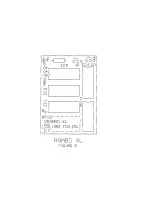
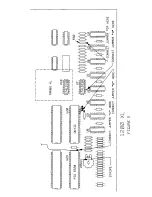
JP1-JP3 are the jumper plugs on your RAMBO XL board. For
JP1-JP3, the '0' indicates that the jumper position should not
match the bar on the silk screen legend. The '-' indicates that the
jumper should match that of the silk screen legend. The '0' (not
-') is the most common setting for the 800XL and also the way
we ship RAMBO XL from the factory. (See Figure 3.)
For A-D, the 'Y' indicates that this jumper needs to be connected to
your computer and the 'N' indicates that no connection is
necessary.
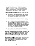
NOTE: A-D refers to the solder filled pads on the RAMBO XL board
marked A-D. You will solder a piece of wire from these pads to the
designated points on the computer board as required.
800XL Jumper Wire Connections
(see Table 1 and Figures 3 & 4)
A no connection, 1200XL only
B no connection, 1200XL only
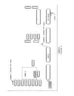
C this is connected to the refresh line only when you have the
old C012296 version ANTIC. This is to be connected to pin
8 of the ANTIC or soldered to the common pad which is the
upper right of ANTIC. (See Figure 4.)
D this is the RA8 line and must be attached on all
installations. RA8 is the extra address line needed for the
256K DRAMS. Jumper D must be connected to the right
side of R32 which is at the top of the column of DRAMS.
Just solder the wire to the right side of this resistor. (See
Figure 4.)
7


