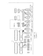
Chapter 4-Installation for 1200XL
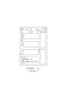
NOTE: A-D refers to the solder filled pads on the RAMBO XL board
marked A-D. You will solder a piece of wire from these pads to the
designated points on the computer board as required. When
RAMBO XL is packaged, JP1-JP3 are set in the most common
position for 800XL installations. Generally, these jumper plugs
should all be moved when making the 1200XL installation.
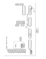
Remove the 64K DRAMS and replace them with your 256K DRAMS.
These ICs are very static sensitive so make sure you are grounded
while moving them around. Remove the old DRAMS with a small
screwdriver. Notice the notch goes to the left. Replace them with
the new 256K DRAMS making sure they also have the notch to the
left.
Replace U10 with RAMBO XL.
Remove U10. Carefully plug RAMBO
XL into its socket with the long part of the board towards the rear.
Do not plug it in backwards. If it is plugged in correctly, you will
still be able to see the top of U7.
11


