background image


©2009 IC Realtime, Inc. 

71 

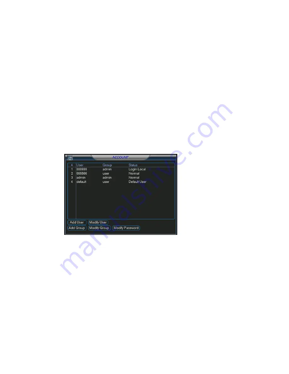
5.5.5  Account 

Here is for the account management console.  Here you can: 

  Add new users 

  Modify users 

  Add groups  

  Modify groups 

  Modify passwords 

For account management, please note: 

  Accounts are grouped into users and groups. There is no limit to the number of 

groups or users.  

  By default, users are grouped as either admin or user. 

  The user name and group name can consist of six characters. Each user name 

must be unique. There are three default user accounts.  Each account’s default 
password matches the user name: The “

Admin

” login has full administrative 

rights on the DVR.  The “

User

“ login has viewing and playback rights.  Finally, 

the “

Guest

” login allows only live viewing access. 

  One user can belong to only one group. User rights can not exceed group rights. 

Once finished, click save to save your account setup. 


Figure 5-32  


5.5.6  Auto Maintain 

Here you can configure auto-reboot time and the auto-delete of old files. See Figure 
5-33. 
You can select the options from the dropdown list.  
Please click O.K button after you completed the setup. 

Summary of Contents for Max 4

Page 1: ... 2009 IC Realtime Inc 1 Standalone DVR User s Manual Max 4 ...

Page 2: ...4 2 2 2 Connection Sample 15 2 3 2 3 2 3 2 3 Remote Control Remote Control Remote Control Remote Control 16 2 4 2 4 2 4 2 4 Mouse Control Mouse Control Mouse Control Mouse Control 17 2 5 2 5 2 5 2 5 Virtual K Virtual K Virtual K Virtual Keyboard Front Panel eyboard Front Panel eyboard Front Panel eyboard Front Panel 18 2 5 1 Virtual Keyboard 18 2 5 2 Front Panel 18 3 3 3 3 INSTALLATION AND CON INS...

Page 3: ...io Connecting Audio Input Output Bidirectional Audio Connecting Audio Input Output Bidirectional Audio Connecting Audio Input Output Bidirectional Audio 22 3 7 1 Audio Input Audio Output 22 3 7 2 Alarm Input and Relay Output 23 3 7 3 Alarm Input 23 3 7 4 Alarm Output 23 3 7 5 Alarm Input and Output Details 23 3 7 6 Relay Output Description 24 3 8 3 8 3 8 3 8 RS232 RS232 RS232 RS232 26 3 9 3 9 3 9 ...

Page 4: ... 4 6 4 6 4 6 Alarm Setup and Alarm Activation Alarm Setup and Alarm Activation Alarm Setup and Alarm Activation Alarm Setup and Alarm Activation 42 4 6 1 Alarm Menu 42 4 6 2 Alarm setup 42 4 7 4 7 4 7 4 7 Backup Backup Backup Backup 44 4 7 1 Detect Device 44 4 7 1 Backup 45 4 8 4 8 4 8 4 8 PTZ Control and Color Setup PTZ Control and Color Setup PTZ Control and Color Setup PTZ Control and Color Set...

Page 5: ...5 3 5 3 Setting Setting Setting Setting 54 5 3 1 General 54 5 3 2 Encode 56 5 3 3 Schedule 57 5 3 4 RS232 57 5 3 5 Network 58 5 3 6 Alarm 65 5 3 7 Detect 65 5 3 8 Pan Tilt Zoom 65 5 3 9 Display 65 5 3 10 Default 67 5 4 5 4 5 4 5 4 Search Search Search Search 68 5 5 5 5 5 5 5 5 Advanced Advanced Advanced Advanced 68 5 5 1 HDD Management 68 5 5 2 Abnormity 69 5 5 3 Alarm Output 70 5 5 4 Manual Recor...

Page 6: ...9 Flip 79 7 7 7 7 WEB CLIENT OPERATION WEB CLIENT OPERATION WEB CLIENT OPERATION WEB CLIENT OPERATION ERROR BOOKMARK NOT DEFINED 7 1 7 1 7 1 7 1 Network Connection Network Connection Network Connection Network Connection Error Bookmark not defined 7 2 7 2 7 2 7 2 Login Login Login Login Error Bookmark not defined 7 2 1 Real time Monitor Error Bookmark not defined 7 2 2 PTZ Error Bookmark not defin...

Page 7: ...Live Cameras Viewing Live Cameras Error Bookmark not defined 9 9 9 9 RS232 OPERATION RS232 OPERATION RS232 OPERATION RS232 OPERATION ERROR BOOKMARK NOT DEFINED 9 1 9 1 9 1 9 1 Network Connection Network Connection Network Connection Network Connection Error Bookmark not defined 9 2 9 2 9 2 9 2 Keyboard Keyboard Keyboard Keyboard Error Bookmark not defined 10 10 10 10 FAQ FAQ FAQ FAQ ERROR BOOKMARK...

Page 8: ... BOOKMARK NOT DEFINED Welcome Thank you for purchasing our DVR This operating manual is designed to be a reference tool for the installation and operation of your system Here you can find information about this series DVR its features and functions as well as a detailed menu tree Before installation and operation please read the following safeguards and warnings carefully ...

Page 9: ...t place objects on top of the DVR 4 Qualified engineers needed All examination and repair work should be done by qualified service engineers We are not liable for any problems caused by unauthorized modifications or attempted repair 5 Environment The DVR should be installed in a cool dry place away from direct sunlight flammable materials and water 6 Accessories Be sure to use all the accessories ...

Page 10: ...ed dome 3D intelligent positioning function supported 4 channel audio inputs and bidirectional talk supported Alarm triggering screen tips buzzer PTZ preset e mail FTP upload Powerful network software built in web server EPSS Networking access for remote live viewing recording playback setting system status event log e mail ftp function 1 2 1 2 1 2 1 2 Specification Specification Specification Spe...

Page 11: ...el 6 is highest Trigger recording PTZ preset tour alarm Video Loss Trigger recording PTZ preset tour alarm Camera masking Trigger recording PTZ preset tour alarm Alarm Input 4 channel programmable ground manual open closed Trigger recording PTZ movement tour alarm e mail FTP Relay output 3 channel 30VDC 1A NO NC form C Hard Disk Hard Disk 1 SATA HDD port 1 HDD supported Space Occupation Audio 14 4...

Page 12: ...ation Monitor PTZ control playback system setting file download log information Auxiliary Interface USB Interface Two USB 2 0 ports one for mouse control one for backup RS232 Keyboard PC communication RS485 PTZ control Environmental Power Consumption 25W Working Temperature 0 55 14 F 130 F Working Humidity 10 90 Atmosphere Pressure 86kpa 106kpa Dimension 1U 375x285x45mm W D H Weight 3 25Kg Mountin...

Page 13: ...ayback mode reverse play video In text box input number 6 4 Fast play In playback mode click this button to switch between various fast play speeds and normal playback In text box input number 7 5 Slow play In playback mode click this button to switch between various slow play speeds and normal playback In text box input number 8 6 Next I In playback mode play the next video In text box input numb...

Page 14: ...ropdown list modify current setup In monitor mode click this button to go to the 1st channel 1 or 4th channel Single channel monitor mode In text box input mode press SHIFT and then use up down key to input number 1 or 4 In the main menu or sub menu interface click left or right key to move cursor In playback mode Click left right key to select corresponding option in the function menu In monitor ...

Page 15: ...ohms 3 RS232 port VGA port 4 Mouse network interface Two USB 2 0 high speed ports 10M 100M self adaptable Ethernet port 5 Main function section C1 O1 Alarm output 1 public port C2 O2 Alarm output 2 public port 12V 12V 100mA output A B RS485 port 1 4 Alarm input port G Ground 6 Power control section Power socket AC 100V 240V 50HZ 60HZ Please pay attention to the ethernet connection you need to use ...

Page 16: ...Realtime Inc 16 Figure 2 3 2 3 2 3 2 3 2 3 Remote Con Remote Con Remote Con Remote Control trol trol trol The remote control interface is shown as in Figure 2 4 Figure 2 4 Serial Number Function 1 remote switch ...

Page 17: ...status Expand drop down menus Left click mouse In the input box you can select different input methods By left clicking the corresponding button on the panel you can input upper and lower case letters numbers and symbols Also note the _ represents a space and works as a backspace or delete To input symbols you can use the corresponding numeral in the front panel For example click number 1 to input...

Page 18: ...p or page down Move mouse Control the mouse cursor Select motion detection zone Click Drag mouse Select privacy mask zone 2 5 2 5 2 5 2 5 Virtual Keyboard Front Panel Virtual Keyboard Front Panel Virtual Keyboard Front Panel Virtual Keyboard Front Panel 2 5 1 Virtual Keyboard The system supports Alphanumeric upper and lower case and symbols input Move the cursor to the text column and you will see...

Page 19: ...tallation 3 2 1 Choose HDDs We recommend Seagate IBM Hitachi HDD of 7200rpm or higher 3 2 2 Calculate HDD Size You can use 120G 1500G HDD to guarantee higher recording durations The formula of total HDD size is Total Capacity MB Camera Amount Recording Hours HDD Usage Per Hour M h H 264 compression is ideal for standalone DVRs It can save more than 30 HDD capacity over MPEG4 part 1 When you calcul...

Page 20: ... cord 3 3 3 3 3 3 3 3 D D D Desktop esktop esktop esktop M M M Mounting ounting ounting ounting 3 3 1 Desktop Mounting To prevent surface damage please make sure that the rubber feet are securely installed on the four corners of the bottom of the unit Position the unit to allow for cable and power cord clearance at the rear of the unit Please make sure that the air flow around the unit is not obst...

Page 21: ...coaxial cable to the camera or other analog video source 2 Connect the coaxial cable to the video in connector on the rear panel Please refer to Error Reference source not found for more information NOTE You need to use a BNC installation tool to connect coaxial cables to the rear panel Figure 3 1 3 5 2 Connecting Video Output This section provides information about physically connecting video dis...

Page 22: ...t The DVR encodes audio and video signals simultaneously which lets you control audio at the monitored location To set up audio 1 Make sure your audio input device matches the RCA input level If the device and RCA input levels do not match audio distortion problems may occur 2 Make sure the audio connector is wired as follows 3 Connect a line input device or pre amplified microphone to the audio c...

Page 23: ...l is needed for alarm input If you need to connect two units or one DVR and other device use a relay to separate them Please refer to Figure 3 4 for more information Figure 3 4 3 6 4 Alarm Output Do not connect alarm output ports directly with high power loads no more than 1 A You can use the co contactor to realize the connection between the alarm output port and the load Please refer to Figure 3...

Page 24: ...ND end of the alarm detector Provide external power to the alarm detector Please parallel connect the Ground of the DVR and the ground of the alarm detector Please connect the NC port of the alarm sensor to the DVR alarm input ALARM If you need to reset the touched off alarm remotely you can use DVR to supply controllable 12 V power to the alarm detector such as the smoke detector Use the same gro...

Page 25: ...Figure 3 8 Please refer to Figure 3 9 for alarm output module information Figure 3 9 Relay Specification Model JRC 27F Material of the touch Silver Rated switch capacity 30VDC 2A 125VAC 1A Maximum switch power 125VA 160W Maximum switch voltage 250VAC 220VDC Rating resistance load Maximum switch currency 1A between touches with same polarity 1000VAC 1minute 50 60Hz Insulation between touches with d...

Page 26: ...d into one of the RS232 ports on the DVR or through network 3 8 3 8 3 8 3 8 RS485 RS485 RS485 RS485 When the DVR receives a camera control command it transmits that command up the UTP cable to the PTZ device RS485 is a single direction protocol the PTZ device can t return any data to the unit To enable the operation connect the PTZ device to the RS485 A B input on the DVR Since RS485 is disabled b...

Page 27: ... 2009 IC Realtime Inc 27 Figure 3 10 ...

Page 28: ...sword admin administrator local and remote Username guest Password guest low authority user local and remote Username user Passwords user low authority user who can monitor live feed playbacks and backups Username default Password default hidden user view cameras only For your system security please modify password after your first login You can input your password by using the front panel keys th...

Page 29: ...east 3 seconds system will stop all operations Then you can click the power button in the rear panel to turn off the DVR 4 1 4 Auto Resume after Power Failure The system can automatically backup video and resume previous working status after power failure 4 1 5 Replace CMOS Battery Please make sure to use battery model CR 2032 We recommend you replace it regularly such as once every 2 3 years to g...

Page 30: ...o to the Main Menu Advanced Manual Record In live viewing mode you can press the record button on the front panel You can also press record on the remote control 4 2 2 2 Basic operation There are three statuses schedule manual stop Highlight icon to select corresponding channel Manual the highest priority After manual setup all selected channels will begin continuous recording Schedule channel rec...

Page 31: ...sly defined in the schedule Main menu Setting Schedule The corresponding recording LED on the front panel will turn on Figure 4 7 All channel manual record Highlight ALL after Manual See Figure 4 8 When the system is in manual recording all scheduled recordings previously defined will be ignored You will see the recording LED light on the front panel turn on and the system will begin manual record...

Page 32: ...le interface Main menu Setting Schedule Figure 4 9 4 3 4 3 4 3 4 3 Search Search Search Search Playback Playback Playback Playback 4 3 1 Search Menu There are two ways for you to go to search menu Click Pause Play in the remote control Click search in the main menu The search screen is shown below ...

Page 33: ...ime Inc 33 Figure 4 10 Usually there are three file types R regular recording file A external alarm recording file M motion detection recording file There are several playback windows The DVR support 1 4 ch playback ...

Page 34: ...page You can double click file name to view the file content 4 3 2 2 Accurate playback Input time h m s in the time column and then click the search button Your results will appear at the top 4 3 2 3 Synchronized playback function when playback During a playback you can click a number key The system can switch to the corresponding channel video of the same time 4 3 2 4 Digital zoom When the system...

Page 35: ...urrent channel 4 3 2 7 Fast forward fast backward and frame by frame playback Special Functions of Shuttle and Jog Illustration Remarks Fast forward outer ring clockwise In playback mode turn the shuttle outer ring clockwise one round to view in fast level 1 Turn it two rounds to get fast level 2 You can continue turning it to get different speeds Fast backward outer ring counter clockwise In play...

Page 36: ...e n normal playback mode slowly turn the jog inner dial clock wise to view frame by frame counter clock wise to view single frame playback When system is in backward play or frame by frame playback mode you can click play to go to normal playback Note All the operations here such as playback speed channel time and progress have relationship with hardware version Some series DVRs do not support som...

Page 37: ...ult 24 hour regular mode You can set record type and time in the schedule 4 4 1 Schedule Menu In the main menu from setting to schedule you can see schedule interface See Figure 4 12 There are three recording types R Regular MD Motion detection A Alarm Figure 4 12 4 4 2 Basic Operation There are a total six periods See Figure 4 12 Channel Select the channel number first You can select all if you w...

Page 38: ...dule Latch when detection is complete the auto trigger continues detecting for a specified time The value ranges from 10 300 seconds Region Select region from Figure 4 14 and you can specify a motion detection zone There are 396 PAL 330 NTSC small zones Sensitivity Ranges from 1 6 1 is the lowest and 6 is the highest level of sensitivity Show message You can choose to pop up a message to alarm you...

Page 39: ...egion for motion detection Click Fn to switch between active passive motion detection The red grid squares are your active motion zones everything else is a passive zone After competing setup please press enter to exit or right click to return to the previous menu Figure 4 13 Figure 4 14 ...

Page 40: ...You can see an interface is shown as in Figure 4 18 This function allows you to be informed when video loss occurs You can enable alarm output channel and then enable show message function also Channel select the channel you want to configure for motion detection Event type from the dropdown list you can select the detection type ...

Page 41: ... business days or non business days In Figure 4 16 click set to see the interface shown in Figure 4 17 Anti dither Here you can set anti dither time Alarm output when alarm occurs the DVR enables peripheral alarm devices Tour Here you can enable the tour function when alarm occurs It is a one window tour Please go to chapter 5 3 9 Display for tour interval setup Figure 4 18 4 5 4 Camera Masking Wh...

Page 42: ... set anti dither time Alarm output when alarm occurs the DVR enables peripheral alarm devices Tour Here you can enable the tour function when alarm occurs It is a one window tour Please go to chapter 5 3 9 Display for tour interval setup Note In this interface the copy paste function is only valid for the same event type For example you can not copy a channel setup in video loss mode to camera mas...

Page 43: ...ge System can provide pop up notifications in the local host screen if this function is enabled Record channel you can select proper channel to record alarm video Multiple choices At the same time you need to set alarm record in schedule interface Main Menu Setting Schedule and select schedule record in manual record interface Main Menu Advance Manual Record Latch This is where you can set proper ...

Page 44: ...kup devices such as CD RW DVD drives USB backup and network downloads Here we will introduce a USB backup first You can refer to Chapter 7 Web Client Operation for network downloads backup operations 4 7 1 Detect Device Click backup button you can see an interface is shown as in Figure 4 24 Here is for you to view devices information ...

Page 45: ...ed device See Figure 4 25 The system will only backup files marked with a before the channel name You can use Fn or cancel to delete s after the file serial number Click backup when you re ready to back files to the selected device There is a process bar for you reference After the backup completed you can see a dialogue box prompting successful backup Figure 4 25 Click start and the system will b...

Page 46: ...general interface Main Menu Setting General You can visit our website to view listed CD ROM type 4 8 4 8 4 8 4 8 PTZ Control and Color Setup PTZ Control and Color Setup PTZ Control and Color Setup PTZ Control and Color Setup Note All the operations here are based on PELCO D1 protocol 4 8 1 Cable Connection Please follow the procedures below to go on cable connection Connect the dome s RS485 cable ...

Page 47: ...e is 9600 Data bits select corresponding data bits Default value is 8 Stop bits select corresponding stop bits Default value is 1 Parity there are three options odd even none Default setup is none Figure 4 27 After completing all the setups please click save button In single window display mode right click mouse or Fn on the front panel or press Fn on the remote control to highlight pan tilt zoom ...

Page 48: ...e single screen mode Drag the mouse in the screen to adjust section size It can realize PTZ automatically Figure 4 31 Here is a sheet for you reference Name Function key function Shortcut key Function key function Shortcut Key Zoom Near Far Focus Near Far Iris close Open 4 9 4 9 4 9 4 9 Preset Preset Preset Preset P P P Patrol atrol atrol atrol P P P Pattern attern attern attern Scan Scan Scan Sca...

Page 49: ... Auto pan Flip Reset Page switch Figure 4 33 Note The following setups are usually operated in the Figure 4 29 Figure 4 32 and Figure 4 33 4 9 1Preset Setup In Figure 4 29 use the eight directional arrows to adjust camera to the proper position In Figure 4 32 click preset button and then input the desired preset number The interface is shown as in Figure 4 34 Now you can add this preset to one tou...

Page 50: ...l tour For each patrol tour you can input max 80 presets Figure 4 35 4 9 4 Activate Patrol tour In Figure 4 32 input patrol tour number in the No blank and click patrol 4 9 5 Pattern Setup In Figure 4 32 click pattern and then click begin to start the pattern s recording The interface is shown as in Figure 4 36 Then you can go to Figure 4 29 to modify zoom focus and iris Go back to Figure 4 36 and...

Page 51: ...mera s left limit Next go to Figure 4 37 and click left limit Repeat the above procedures to set the right limit Figure 4 37 4 9 8 Activate Auto Scan In Figure 4 33 click Auto Scan to begin the auto scan Correspondingly the auto scan button becomes to stop button Click stop button to terminate scan operation 4 10 4 10 4 10 4 10 Flip Flip Flip Flip In Figure 4 33 click page switch button you can se...

Page 52: ... 2009 IC Realtime Inc 52 Figure 4 38 ...

Page 53: ...ol 5 1 5 1 5 1 5 1 Menu Menu Menu Menu T T T Tree ree ree ree This series DVR menu tree is shown as below 5 2 5 2 5 2 5 2 Main Main Main Main M M M Menu enu enu enu After you are logged in the system main menu is shown as below See Figure 5 1 There are a total six icons Search Information Setting Backup Advanced and Shutdown Move the cursor to highlight the icon and then left click mouse to enter ...

Page 54: ... Date format there are three types YYYY MM DD MM DD YYYY or DD MM YYYY Date separator there are three denotations to separate date dot line and slash DST Here you can set DST time and date Enable the DST function and then click set button You can see an interface is shown as in Figure 5 4 Here you can set the start time and end time by setting the corresponding week setup In Figure 5 4 click date ...

Page 55: ...Pack duration Here is where you specify the duration of recorded files Default value is 60 minutes DVR No When you are using one remote control to control several DVRs you can give a number to each DVR for your management Video standard There are two formats NTSC and PAL Auto logout Here is for you to set auto logout interval once login user remains inactive for a specified time Value ranges from ...

Page 56: ...DVRs only support PAL 25f s Video audio you can enable or disable the video audio Overlay click overlay you can see an interface is shown as in Figure 5 7 Cover area Privacy mask Here is for you to set window masking regions You can drag the mouse to set the proper section size Preview monitor privacy mask has two types Preview means the privacy mask zone can not be viewed by user when system is i...

Page 57: ... to select The console setting is used to upgrade the device via a serial connection The keyboard is for you to use a special keyboard to control the device Baud rate You can select proper baud rate Data bit You can select proper data bit Stop bit There are three values 1 1 5 2 Parity there are three choices none odd even After completing setup click save button The system will return to the previ...

Page 58: ...ed to disable DHCP function to view current IP information Besides when PPPoE is operating you can not modify IP Subnet mask Gateway TCP port Default value is 37777 System server port 37778 is reserved for network UDP use UDP port Default value is 37778 HTTP port Default value is 80 Max connection The system supports a maximum of 10 users 0 means there is no connection limit Transfer mode Here you...

Page 59: ...uble click the item to go to setup interface Figure 5 10 5 3 5 2 IP Filter The IP Filter interface is shown as in Figure 5 11 You can specify individual IP addresses to have access to the DVR System supports a maximum of 64 IP addresses Please note after you enabled this function only the IP listed below can access current DVR If you disable this function all IP addresses can access current DVR ...

Page 60: ... four bit of the first byte 1110 Reserved local multiple cast group address 224 0 0 0 224 0 0 255 TTL 1 When sending out telegraph For example 224 0 0 1 All systems in the sub net 224 0 0 2 All routers in the sub net 224 0 0 4 DVMRP router 224 0 0 5 OSPF router 224 0 0 13 PIMv2 router Administrative scoped addressees 239 0 0 0 239 255 255 255 Private address space Like the single broadcast address...

Page 61: ...tup You will need to install an SNTP server Such as Absolute Time Server in your PC first or at least have one running on your network NTP setup interface is shown as in Figure 5 14 Host IP Input your PC address Port This series DVR supports TCP transmission only Port default value is 123 Update interval minimum value is 15 Unit minute Time zone select your corresponding time zone here Here is a s...

Page 62: ...DNS menu input your PPPoE name you get from you ISP and server IP PC with DDNS Click save button system prompts for rebooting to get all setups activated After rebooting open IE and input as below http DDNS server IP virtual directory name webtest htm e g http 10 6 2 85 DVR _DDNS webtest htm Now you can open DDNSServer web search page Figure 5 15 5 3 5 7 Alarm Server You can configure the alarm in...

Page 63: ...rmissions to the FTP upload user See Figure 5 17 Figure 5 17 You can use a PC or FTP login tool to test if the setup is right or not For example you can login user with ZHY to FTP 10 10 7 7 and then test if it can modify or delete the folder or not See Figure 5 18 Figure 5 18 The system also supports the upload of multiple DVRs to one FTP server You can create multiple folders under this FTP In Fi...

Page 64: ...video available Here you can input FTP server address port and etc Figure 5 20 File length upload file length When the value is larger than the actual file length the system will upload the whole file When this value is smaller than the actual file length system only uploads the set length and automatically ignores the left section When interval value is 0 the system will upload all corresponding ...

Page 65: ...even After completing setup click save The system will return to the previous menu For a detailed setup please refer to Chapter 4 9 preset patrol pattern scan Figure 5 22 5 3 9 Display The Display setup menu is shown below See Figure 5 23 Transparency Here is for you to adjust the transparency The value ranges from 128 to 255 Channel name Here is for you to modify channel names Please note all of ...

Page 66: ...r tour enabled stands for tour disabled Motion tour type System supports either 1 4 view tour Alarm tour type System supports either 1 4 view tour Please highlight icon to select the corresponding function After completing all the setups please click save button system goes back to the previous menu Figure 5 23 In Figure 5 23 click modify button after channel You can see an interface is shown as i...

Page 67: ...fault Here you can restore your system to factory default settings See Figure 5 26 Select all General Encode Schedule RS232 Network Alarm Detect Pan tilt zoom Display Channel name Please highlight icon to select the corresponding function After completing all the setups please click save button system goes back to the previous menu Warning System menu color language time display mode video format ...

Page 68: ...n interface is shown as in Figure 5 27 There are total seven submenus HDD management alarm output abnormity manual record account auto maintain and TV adjust Figure 5 27 5 5 1 HDD Management Here you can view and manage hard disks See Figure 5 28 You can set proper mode for each hard disk from the dropdown list After completing all the setups please click save button system needs to reboot to get ...

Page 69: ...tup Please highlight icon to select the corresponding function You can manually enable one or more alarm setups Alarm channel number ranges from 1 to 6 Delay value is from 0 to 240 seconds After completing setup click save The system will need to reboot to apply the changes Figure 5 29 5 5 2 Abnormity The Abnormity interface is shown as in Figure 5 30 ...

Page 70: ...ly delays the specified seconds in turning off alarm and activated output after the external alarm ends Show message the system can pop up a message in the local screen to alert you when an alarm occurs Figure 5 30 5 5 3 Alarm Output Here you can manually configure alarm outputs Please highlight icon to select the corresponding alarm output See Figure 5 31 After completing setup click OK Figure 5 ...

Page 71: ...must be unique There are three default user accounts Each account s default password matches the user name The Admin login has full administrative rights on the DVR The User login has viewing and playback rights Finally the Guest login allows only live viewing access One user can belong to only one group User rights can not exceed group rights Once finished click save to save your account setup Fi...

Page 72: ...just each item Please click OK button after you have completed the setup Figure 5 34 5 6 5 6 5 6 5 6 I I I Information nformation nformation nformation Here you can view system information There are a total of five submenus HDD hard disk information BPS data stream statistics Log and version and online user See Figure 5 35 Figure 5 35 ...

Page 73: ...is a hard disk conflict check weather the hard disk time and system time are the same If not go to Setting and then General to modify the system time At last reboot the system to solve this problem If a disk is damaged the system shows as Figure 5 36 5 6 2 BPS Here you can view current video data stream KB s and occupied hard disk storage MB h See Figure 5 37 Figure 5 37 5 6 3 Log Here you can vie...

Page 74: ...arch to view the log files You can use page up down to view the additional files Figure 5 38 5 6 4 Version Here you can view some version information See Figure 5 39 Channel Alarm in Alarm out System version Build Date Figure 5 39 5 6 5 Online Users Here you can manage online users See Figure 5 40 You can disconnect one user or block one user if you have the appropriate system rights ...

Page 75: ...dropdown menu is shown as in Figure 5 41 Logout menu user log out menu You need to input password when you login the next time Restart application reboot DVR Shutdown system shuts down and turns off power Restart system system begins rebooting Switch user you can use another account to log in Figure 5 41 ...

Page 76: ...lt Zoom the interface is shown in Figure 6 2 Here you can set the following items Zoom Focus Iris Click icon and to adjust zoom focus and Iris Figure 6 2 In Figure 6 2 click the directional arrows See Figure 6 3 to adjust the PTZ s position There are total eight directional arrows Note there are only four directional arrows in DVR front panel Figure 6 3 6 1 1 3D Intelligent Positioning Key In the ...

Page 77: ...trol P P P Pattern attern attern attern Bo Bo Bo Border rder rder rder F F F Function unction unction unction In Figure 6 2 click the set button The interface is shown as below Here you can set the following items Preset Tour patrol Pattern Border Figure 6 5 In Figure 6 2 click the page switch button you can see an interface is shown as in Figure 6 6 Here you can activate the following functions P...

Page 78: ...u desire In Figure 6 5 click preset and input preset number The interface is shown as in Figure 6 7 Add this preset to one patrol number Figure 6 7 6 2 2 Activate Preset In Figure 6 6 input your desired preset number in the No ____ and click preset to activate it 6 2 3 Tour Setup In Figure 6 5 click Patrol button you can see an interface is shown as in Figure 6 8 Input preset number and then add t...

Page 79: ...esired pattern preset mode value in the No _____ and then click pattern to activate it 6 2 7 Border Setup In Figure 6 5 click border you can see an interface is shown as in Figure 6 10 Go to Figure 6 2 and use the directional arrows to select the camera s left limit Now go back to Figure 6 10 and click left limit Repeat the above procedures to set the right limit Figure 6 10 6 2 8 Activate Border ...

Page 80: ... 2009 IC Realtime Inc 80 Click page switch button again system goes back to Figure 6 2 Figure 6 11 ...

Page 81: ...ntrol Navigate to Start Control Panel User Accounts Double click user accounts and then disable user account control You will need to restart after this The system can automatically download the latest web control and the new version can overwrite the previous one If you want to un install the web control run uninstall web bat Note before you un install close all web pages otherwise the un install...

Page 82: ...nstallation you will have the interface shown below See Figure 7 3 Input your user name and password Default factory name is admin and password is admin Note For security reasons you should modify your password after your first login Figure 7 3 ...

Page 83: ...r 7 2 3 and you can also select picture path and record path Section 4 real time monitor window Note current preview window is outlined by a green rectangle Section 5 Here you can control the window layout You can also select video priority between fluency or real time Supported window layouts include full screen 1 window 4 window 6 window 8 window 9 window 13 window 16 window 20 window 25 window ...

Page 84: ...esize or switch to full screen mode 3 Local record When you click local record the system will begin recording to your PC and this button will become highlighted You can go to system local record to set video file path 4 Capture picture You can take a snapshot of important video All images are stored in the system client folder download picture default 5 Audio Turn on or off audio It has no relati...

Page 85: ...re 7 9 Figure 7 9 7 2 2 PTZ Before operating a PTZ make sure you have configured the PTZ protocol address and Baud Rate Refer to chapter 7 3 2 Setting Pan Tilt Zoom Click the PTZ button you will see the interface shown in Figure 7 10 Figure 7 10 7 2 2 1 Direction Key In Figure 7 10 there are eight direction keys You can click this icon to display or hide the PTZ control platform ...

Page 86: ...ed 1 7 2 2 3 Zoom Focus Iris Here is a sheet for reference Name Function key Function Function key Function Zoom Near Far Focus Near Far Iris close Open Click the triangle icon in Figure 7 10 you will see the following interface See Figure 7 11 Figure 7 11 In Figure 7 11 click PTZ set you will see the following interface See Figure 7 12 ...

Page 87: ...o Figure 7 11 to begin camera operation Once finished you can click stop record Now you have set one pattern 7 2 2 6 Preset In Figure 7 12 move the camera to your desired location and then input a preset value Click add to set this as a preset location 7 2 2 7 Auto tour In Figure 7 12 input an auto tour value and a preset value Click add to set the preset in the tour By repeating the above procedu...

Page 88: ...an select one channel and then adjust its brightness contrast hue and saturation The selected channel has a green border Alternatively you can click default to use the default color setup Figure 7 14 7 2 4 Picture Path and Record Path Click more in Figure 7 14 and you will see the interface shown in Figure 7 15 Figure 7 15 ...

Page 89: ...7 Clicking reboot will prompt you to reboot the system Click OK to continue 7 2 5 Menu Interface Switch Put your mouse on the PTZ control bar until you see the following icon See Figure 7 18 Figure 7 18 Left click your mouse and then drag it to the channel control status bar You will notice the two menus interface switched positions See Figure 7 19 You can compare the following interface with Figu...

Page 90: ... 3 7 3 7 3 7 3 Setup Setup Setup Setup In the main window click Setup you will see an interface as shown in Figure 7 20 Figure 7 20 7 3 1 System Information Click device configuration and you will see the following interface See Figure 7 21 ...

Page 91: ...gure 7 21 Version Click version and you will see corresponding HDD information for reference See Figure 7 22 Figure 7 22 HDD Information Here you can view the number of HDD s HDD status total volume and free space See Figure 7 23 ...

Page 92: ...lowing items General Encode setup Schedule RS232 Network MUL DDNS FTP Alarm setup Detect Pan Tilt Zoom Tool Note setups for different device series may vary Refer to the corresponding user s manual General General interface is shown as in Figure 7 25 System time This is where you can modify the system time click Save after your changes Date format Here you can select the date format from the dropd...

Page 93: ...R now Video standard NTSC for your reference only Figure 7 25 Encode Encode setup includes the following items See Figure 7 26 Here you can select Channel This is where you can select a channel Channel name Modify channel name Data stream Regular and extra data stream AV enable Video Audio System only displays video by default You need to manually enable audio function Bit rate There are two optio...

Page 94: ...s Record types includes regular record R motion detection MD and alarm A Channel select the channel number you desire Week you can select from the dropdown list Prerecord system can record the three to five seconds video before activating the record operation into the file Depends on data size Period There are six periods for you to define Click set next to the corresponding period See Figure 7 28...

Page 95: ...me Inc 95 Figure 7 27 Figure 7 28 Tip After you finished setup for one channel you can click save as which will pop up the following interface See Figure 7 29 Now you can copy one channels setup to additional channels ...

Page 96: ...lt setup is 80 Transfer Here you can select the priority between fluency latency qualities Enable PPPoE Select PPPoE under the service type to enable PPPoE function and then input PPPoE name and PPPoE password you get from your ISP Internet service provider See Figure 7 30 Once finished click save You will need to restart to activate your configuration After rebooting the DVR will connect to the i...

Page 97: ...booting open IE and input the following http DDNS server IP virtual directory name webtest htm e g http 10 6 2 85 DVR _DDNS webtest htm Now you can open the DDNSServer web search page Figure 7 31 RS232 RS232 includes the following items See Figure 7 32 Function There are various devices for you to select The console setting is used to upgrade the device via a serial connection The keyboard setting...

Page 98: ... 2009 IC Realtime Inc 98 Figure 7 32 Multi DDNS Here you can select a DDNS type to run updates with See Figure 7 33 Figure 7 33 FTP ...

Page 99: ...files File length upload file length When the value is larger than the actual file length the system will upload the whole file When this value is smaller than the actual file length system only uploads the set length and automatically ignores the remaining section When interval value is 0 the system will upload all corresponding files Time period Click set you will see an interface as in Figure 7...

Page 100: ...eriod Click the set button and you will see an interface as shown in Figure 7 36 Here you can set business days and non business days Show message the system can provide pop up notifications on the local screen if this function is enabled Record channel you can select any channel to record alarm video or multiple channels Make sure alarm recording is configured in the schedule menu Main Menu Setti...

Page 101: ...erface as shown in Figure 7 39 In Figure 7 39 click time set you can see an interface is shown as in Figure 7 40 Here you can set time period Sensitivity There are six levels The sixth level has the highest sensitivity Region This option is used to set the motion detection zones The interface is shown as in Figure 7 41 There are 330 zones 22 15 Double right click your mouse and you can go to a ful...

Page 102: ... 2009 IC Realtime Inc 102 Figure 7 38 Figure 7 39 ...

Page 103: ... 2009 IC Realtime Inc 103 Figure 7 40 Figure 7 41 Figure 7 42 ...

Page 104: ...ome address Default value is 8 Note your setup here needs to correspond with your dome address otherwise you can not control the speed dome Baud rate Select the dome baud rate Default setup is 9600 Data bit Default setup is 8 Stop bit Default setup is 1 Parity Default setup is none Figure 7 43 Tool Here you can export or import configuration information See Figure 7 44 Save configuration data Clic...

Page 105: ... includes the following items See Figure 7 46 Account Record control HDD management Video matrix Snap watermark Auto maintain Account Account interface is shown as in Figure 7 46 Here you can add delete users add delete groups modify user or group rights modify users passwords ...

Page 106: ... Inc 106 Figure 7 46 To add a group click add group and you will see the following interface See Figure 7 47 Here you can add one new group and then select corresponding rights for the users contained within this group ...

Page 107: ...ollowing interface See Figure 7 48 Here you can input a new username and password and also select corresponding rights Note Your user and pass have a max limit of 6 characters and are case sensitive Also note that user permissions cannot exceed the group permissions which they are a part of ...

Page 108: ...ord control Here you can adjust the record state for a corresponding channel Alarm output channel Here you can select an alarm output channel to trigger The DVR output channel can not support a large overload It must be less than 1A Too heavy of a current may result in relay damage Use contactor if necessary ...

Page 109: ... management Select the HDD first and then you can see the items on your right have become enabled You can check the corresponding option here See Figure 7 50 After you have completed setup click control HDD you will see the DVR restart itself ...

Page 110: ... 110 Figure 7 50 Auto maintenance Auto maintenance interface is shown as in Figure 7 51 Here you can enable disable auto reboot or the auto deletion of old files The DVR needs to support this operation to function properly ...

Page 111: ...ort this function to work properly From this menu you are able to choose certain channels that you wish to be displayed in a sequential fashion and assign them to a specified matrix output Figure 7 52 Snap Watermark Snap watermark interface is shown as in Figure 7 53 The DVR needs to support this function to work properly ...

Page 112: ... number and a time to search for desired files you wish to playback Click playback the interface is shown as in Figure 7 54 Once you ve chosen a time date and channel click on search The results will appear as in Figure 7 54 Use page up down key to view the search results Double click the file name to start the playback Figure 7 54 ...

Page 113: ...your local PC The playback bar is shown as below See Figure 7 55 1 Play 2 Pause 3 Stop 4 Slow play 5 Fast play Figure 7 55 7 4 1 Download Select one or more files you want to download and then click download The System will pop up a dialogue box asking you to specify a destination directory See Figure 7 56 ...

Page 114: ...ress bar for reference and you will also see the download button becomes a stop button See Figure 7 57 Figure 7 57 7 4 2 Watermark Click watermark to see an interface is shown as in Figure 7 58 Here you can select local recorded file and then click verify to check watermark information You can see corresponding information in the watermark juggle column ...

Page 115: ...e 7 58 7 5 7 5 7 5 7 5 Event Event Event Event Here you can set alarm type and alarm prompt audio file See Figure 7 59 Figure 7 59 7 6 7 6 7 6 7 6 Info Info Info Info Click info to view current web client information See Figure 7 60 ...

Page 116: ...log in interface See Figure 7 61 Figure 7 61 7 8 7 8 7 8 7 8 Un Un Un Un install install install install W W W Web eb eb eb C C C Control ontrol ontrol ontrol You can use web un install tool uninstall web bat to un install web control Note before you un install close all web pages first Otherwise the un installation may result in error ...

Page 117: ...g in Double click the enterprise professional surveillance platform icon from your desktop If it is your first time using the software you will be prompted to choose a language See Figure 8 1 Figure 8 1 After selecting a language click ok to proceed to the login screen Here you can input a user name and password to log in to your selected server The log in interface is shown as in Figure 8 2 If it...

Page 118: ...from the icon group towards the right side above the device list Add a new organization first by clicking the add button on the left hand side Now click add under the device list column to add in the host information of the DVR you wish to connect to Once finished select save in the upper right part of your screen For more information about this operation and more about this software please refer ...

Page 119: ... 2009 IC Realtime Inc 119 ...

Page 120: ...des HD item is for you to select priority between network latency and video fluency Section 4 This is where you can view current help information Section 5 Here is the display for data flux and CPU status Section 6 There are four function buttons PTZ color device and plan For best performance we recommend resolution 1024 768 Select a device name and then click connect disconnect you will connect t...

Page 121: ... 2009 IC Realtime Inc 121 Figure 8 4 Figure 8 5 Connected channel Disconnected channel Add device Add organization structure ...

Page 122: ...orts matrix protocol or not 9 2 9 2 9 2 9 2 Keyboard Keyboard Keyboard Keyboard The control keyboard is very convenient for multi DVR control menu options and PTZ control Select keyboard control from the system setting RS232 function and then set the corresponding baud rate Connect the DVR RS232 port to the converters DSub 25 pin RS232 port and finally specify proper control addresses for all conn...

Page 123: ...the unit Hardware malfunction 3 The system can not detect hard disk These are the possibilities HDD is broken Physically or logically damaged HDD ribbon is damaged HDD cable connection or power connection is loose 4 There is no video seen whether it is one channel multiple channel or all channel outputs These are the possibilities Check all video connections There is either no video input signal o...

Page 124: ...s audio when monitoring but there is no audio with system playback These are the possibilities Setup is incorrect Enable audio recording from the Encode menu 10 Time display is not correct These are the possibilities Setup is incorrect Adjust the current time from the General menu CMOS battery failing or depleted Replace with a CR 2032 style battery 11 DVR can not control PTZ These are the possibi...

Page 125: ...s privacy mask or channel protection setup Current user has no right to monitor DVR local video output quality is poor 15 Network connection is not stable These are the possibilities The network connection itself is unstable IP address conflict MAC address conflict PC or DVR network card is bad 16 Burn error USB backup error These are the possibilities System is using too much CPU resources Stop r...

Page 126: ...ge period is not enough These are the possibilities Camera quality is too low Lens is dirty Camera is installed against the light Camera aperture setup is not correct HDD capacity is not enough Add additional hard drive space HDD is damaged 22 Can not playback the downloaded file These are the possibilities There is no media player Refer to our support page to download the newest version of media ...

Page 127: ...rement is confirmed according to Formula 2 to calculate the storage capacity i m which is storage of each channel needed unit Mbyte i m i q i h i D 2 In the formula i h means the recording time for each day hour i D means number of days for which the video shall be kept Step 3 According to Formula 3 to calculate total capacity accumulation T q that is needed for all channels in the DVR during sche...

Page 128: ...Cruzer Freedom 256M Sandisk Cruzer Freedom 512M Sandisk Cruzer Freedom 1G Sandisk Cruzer Freedom 2G Kingston DataTraveler Ⅱ 1G Kingston DataTraveler Ⅱ 2G Kingston DataTraveler 1G Kingston DataTraveler 2G Maxell USB Flash Stick 128M Maxell USB Flash Stick 256M Maxell USB Flash Stick 512M Maxell USB Flash Stick 1G Maxell USB Flash Stick 2G Kingax Super Stick 128M Kingax Super Stick 256M Kingax Super...

Page 129: ...nded to set USB burner Manufacturer Model Interface Type Sony DRU 835A IDE DVD RW Sony DW Q120A IDE DVD RW Sony DW G120A IDE DVD RW Sony CRX 230AE IDE CD RW Sony CRX 320A IDE CD RW Sony CRX 225E IDE CD RW BenQ DW2000 IDE DVD RW BenQ DW1670 IDE DVD RW BenQ DW1650 IDE DVD RW BenQ DW1640 IDE DVD RW BenQ 5232W IDE CD RW Samsung TS H652M IDE DVD RW LG GH20NS10 SATA DVD RW PIONEER DVR 212D SATA DVD RW S...

Page 130: ...AS2 80G SATA Seagate Barracuda 11 ST3750330AS 750G SATA Seagate Barracuda 11 ST3500320AS 500G SATA Hitachi Deskstar SV3 5 Series 160 250 500 750 1TB SATA Maxtor DiamondMax 20 STM3320820AS 320G SATA Maxtor DiamondMax 20 STM3250820AS 250G SATA Maxtor DiamondMax 21 STM3160211AS 160G SATA Maxtor DiamondMax 21 STM380211AS 80G SATA Maxtor DiamondMax 21 STM340211AS 40G SATA Western Digital Caviar SE WD32...

Page 131: ... 2009 IC Realtime Inc 131 ...

Reviews: