background image

MARGIN

GUIDES

Stay within the yellow 

box. Do not let text go 

beyond, instead move 

to the next column or 

start a new page. 

4  

|  

www.icrealtime.com

2A. INSTALLATION STEPS (IPEL-F50 series)

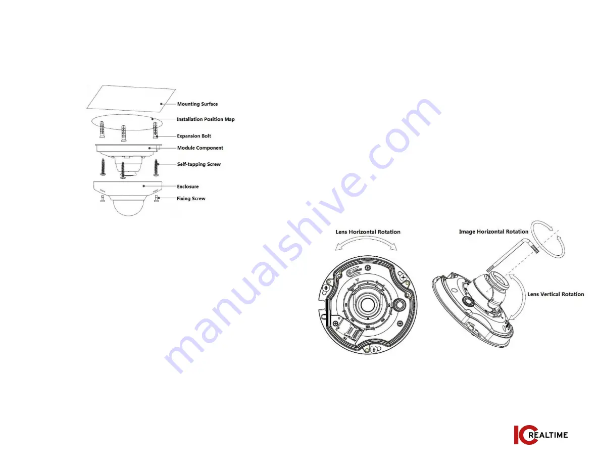
Please follow the steps listed below to install the device. Please refer 

to Figure 2-3 for reference.

Figure 2-3

Step 1 

Take out the installation position map and place it on the 

mounting surface according to the monitoring area.

Step 2 

Mark and drill bottom holes of plastic expansion bolts on the 

mounting surface, insert the expansion bolts into the mounting holes.

Step 3

 If necessary, drill a cable exit hole on the surface according to the 

installation position map if you want to run the cable through the 

installation surface when installing cable. If using the side exit, you will 

need to remove the side cable exit cover on the pedestal to route the 

cable through the notch.

Step 4

 Align the “TOP”direction of the device with the installation 

position map and then align the three screw fixing holes on the device 

pedestal with the three plastic expansion bolt fixing holes on the 

installation surface. Put the three self-tapping screws into the three 

plastic expansion bolts and secure them firmly, and then fix the dome on 

the installation surface.

Adjusting lens angle:

  You can adjust the lens horizontally by hand. Use 

the supplied wrench to adjust the lens vertically as well as to rotate 

image rotation. See Figure 2-4. 

Note:

 The range of lens adjustment angle: vertical rotation direction(0°

+85°), image horizontal rotation direction (0°

+355°), image rotation 

direction (0°

+360°).

Figure 2-4

Summary of Contents for HD 360

Page 1: ...urer recommended Qualified engineers needed All the examination and repair work should be done by the qualified service engineers We are not liable for any problems caused by unauthorized modifications or attempted repair Environment This series network camera should be installed in a cool dry place away from direct sunlight inflammable explosive substances and etc Please keep it away from the electro...

Page 2: ...ich is suitable for the surveillance function in the low illumination environments The waterproof design conforms to the IP67 level It has the sound waterproof function suitable for use in the outdoor environments It can be used standalone or with a network video recorder If used standalone it is able to utilize IC Realtime s software suite including Smart ICRSS IC View and ICRSS Pro This model al...

Page 3: ...mounting plate and pull the cable through the exit hole Match the TOP direction of the camera with that from the installation template Align the 3 mounting plate holes with the plastic anchors from Step 2 Install the ST3 0 screws through the mounting plate holes and into the plastic anchors Figure 2 2 Figure 2 3 Figure 2 4 Step 2 install the included plastic anchor screws See Figure 2 2 Step 4 Tak...

Page 4: ...ing the side exit you will need to remove the side cable exit cover on the pedestal to route the cable through the notch Step 4 Align the TOP direction of the device with the installation position map and then align the three screw fixing holes on the device pedestal with the three plastic expansion bolt fixing holes on the installation surface Put the three self tapping screws into the three plasti...

Page 5: ...ling SD Card Adjust the Micro SD Card to a proper direction shown in Figure 2 5 Step 5 Tighten down locking screws and reinstall camera Please refer to Step 4 in Section 2A for re installation process Figure 3 1 3A OVERVIEW The IP Config tool is used to search the local network for IC Realtime devices as well as modify the IP addresses and upgrading firmware This software can be downloaded at https ...

Page 6: ...d the click the Initialize icon on the bottom left side and follow the process on screen to initialize the device The Operate column will allow you to modify device view device information and link to web browser See figure 3 3 Figure 3 3 To modify the device IP address select one of the devices from the list and then click the pencil icon The dialog box to modify the IP information will populate S...

Page 7: ...ing network camera address to check if connection is OK or not 4B LOGIN AND LOGOUT Open IE or Chrome and input the network camera address in the address bar See Figure 4 1 7 www icrealtime com Figure 4 1 The login interface is shown as below See Figure 4 2 Note If it is your first time logging into the camera and it has not been initialized through the ConfigTool or NVR the camera will need to be in...

Page 8: ...p options depending on the installation type selected See Figure 4 4 8 www icrealtime com Figure 4 3 Web includes several modules monitor channel preview system configuration alarm and etc See Figure 4 3 Live Live video of camera Setup For configuration changes Alarm For monitoring alarm triggers motion detect IVS abnormalities etc Logout Logs out of the camera web GUI Figure 4 4 ...

Page 9: ... movement and changes in vertical angle of view 1P 3 180 expanded rectangular panorama 3 independent sub images Both sub images and the sub box in the expanded rectangular panorama support zoom and movement expanded rectangular panorama supports up and down movement and changes in vertical angle of view 1P 4 180 expanded rectangular panorama 4 independent sub images Both sub images and the sub box...

Page 10: ...u will need to specify the port number after the IP ex http 192 168 1 108 8080 Ensure the correct login credentials are being used The Smart ICRSS software will use the TCP port Make sure you input the correct TCP port number The account is locked Reboot the camera to clear lock out Verify the login to make sure it is correct 5A FAQ P2P status is not connected offline You may need to set device IP t...

Page 11: ...pollution any bodily injury or damage to any assets The consumer is not authorized to process such kind of substances or elements please return to the corresponding local authorities to process according to your local government statutes Note This user s manual is for reference only Slight difference may be found in user interface All the designs and software here are subject to change without pri...

Reviews: