background image

Statement 8:

CAUTION:
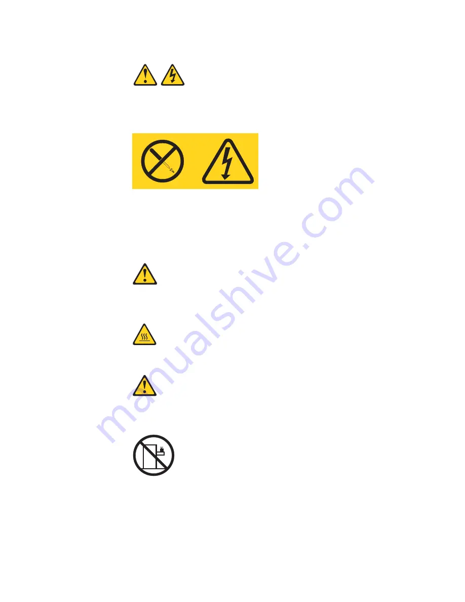
Never remove the cover on a power supply or any part that has the following
label attached.

Hazardous voltage, current, and energy levels are present inside any
component that has this label attached. There are no serviceable parts inside
these components. If you suspect a problem with one of these parts, contact
a service technician.

Statement 12:

CAUTION:
The following label indicates a hot surface nearby.

Statement 26:

CAUTION:
Do not place any object on top of rack-mounted devices.

This server is suitable for use on an IT power-distribution system whose maximum
phase-to-phase voltage is 240 V under any distribution fault condition.

Important: This product is not suitable for use with visual display workplace
devices according to Clause 2 of the German Ordinance for Work with Visual
Display Units.

Safety

xiii

Summary of Contents for x3650 - System M2 - 7947

Page 1: ......

Page 2: ......

Page 3: ...System x3650 M2 Type 7947 Installation and User s Guide...

Page 4: ...ty Information Environmental Notices and User Guide and the Warranty and Support Information documents on the Documentation CD Sixth Edition January 2010 Copyright International Business Machines Corp...

Page 5: ...ssembly LEDs 35 Installation guidelines 36 System reliability guidelines 37 Working inside the server with the power on 37 Handling static sensitive devices 38 Internal cable routing and connectors 39...

Page 6: ...he backup server firmware 119 Using the ServerGuide Setup and Installation CD 119 ServerGuide features 120 Setup and configuration overview 120 Typical operating system installation 121 Installing you...

Page 7: ...ement 139 Avis de conformit la r glementation d Industrie Canada 139 Australia and New Zealand Class A statement 139 United Kingdom telecommunications safety requirement 139 European Union EMC Directi...

Page 8: ...vi System x3650 M2 Type 7947 Installation and User s Guide...

Page 9: ...tuotteen lue turvaohjeet kohdasta Safety Information Avant d installer ce produit lisez les consignes de s curit Vor der Installation dieses Produkts die Sicherheitshinweise lesen Prima di installare...

Page 10: ...tatement is labeled Statement 1 translations for that caution statement are in the Safety Information document under Statement 1 Be sure to read all caution and danger statements in this document befo...

Page 11: ...quipment when there is evidence of fire water or structural damage v Disconnect the attached power cords telecommunications systems networks and modems before you open the device covers unless instruc...

Page 12: ...hium battery replace it only with the same module type made by the same manufacturer The battery contains lithium and can explode if not properly used handled or disposed of Do not v Throw or immerse...

Page 13: ...he device v Use of controls or adjustments or performance of procedures other than those specified herein might result in hazardous radiation exposure DANGER Some laser products contain an embedded Cl...

Page 14: ...he device and the power switch on the power supply do not turn off the electrical current supplied to the device The device also might have more than one power cord To remove all electrical current fr...

Page 15: ...parts contact a service technician Statement 12 CAUTION The following label indicates a hot surface nearby Statement 26 CAUTION Do not place any object on top of rack mounted devices This server is s...

Page 16: ...xiv System x3650 M2 Type 7947 Installation and User s Guide...

Page 17: ...X Architecture technologies which help increase performance and reliability For more information see What your server offers on page 8 and Reliability availability and serviceability features on page...

Page 18: ...ocumentation To check for updates complete the following steps Note Changes are made periodically to the IBM Web site Procedures for locating firmware and documentation might vary slightly from what i...

Page 19: ...e and software requirements The IBM Documentation CD requires the following minimum hardware and software v Microsoft Windows XP Windows 2000 or Red Hat Linux v 100 MHz microprocessor v 32 MB of RAM v...

Page 20: ...appears are listed in order of the most occurrences Click a document to view it and press Crtl F to use the Acrobat search function or press Alt F to use the xpdf search function within the document...

Page 21: ...ing systems The System x and xSeries Tools Center is at http publib boulder ibm com infocenter toolsctr v1r0 index jsp The server might have features that are not described in the documentation that c...

Page 22: ...rdous to you A danger statement is placed just before the description of a potentially lethal or extremely hazardous procedure step or situation Features and specifications The following information i...

Page 23: ...k v Support for remote management presence through an optional virtual media key v One Broadcom dual port 10 100 1000 Ethernet controller with Wake on LAN support and TCP IP Offload Engine TOE support...

Page 24: ...pliant adapters Note The server does not support DOS v Integrated management module The integrated management module IMM combines service processor functions video controller and when an optional virt...

Page 25: ...service processors The diagnostic programs create a merged log that includes events from all collected logs The information is collected into a file that you can send to IBM service and support Additi...

Page 26: ...h support connection to a 10 Mbps 100 Mbps or 1000 Mbps network For more information see Configuring the Gigabit Ethernet controller on page 125 v Large data storage and hot swap capability The server...

Page 27: ...TCP IP offload engine TOE support The Ethernet controllers in the server support TOE which is a technology that offloads the TCP IP flow from the microprocessors and I O subsystem to increase the spee...

Page 28: ...ual systems in a heterogeneous environment By using industry standards IBM Systems Director supports multiple operating systems and virtualization technologies in IBM and non IBM x86 platforms Through...

Page 29: ...s Director The UpdateXpress System Pack Installer The UpdateXpress System Pack Installer detects supported and installed device drivers and firmware in the server and installs available updates For ad...

Page 30: ...g the drive Video connector Connect a monitor to this connector The video connectors on the front and rear of the server can be used simultaneously USB connectors Connect a USB device such as USB mous...

Page 31: ...ED lights the Ethernet icon v Ethernet activity LEDs When any of these LEDs is lit it indicates that the server is transmitting to or receiving signals from the Ethernet LAN that is connected to the E...

Page 32: ...oblem is corrected the server is restarted or a new problem occurs By placing the system error LED indicator in Remind mode you acknowledge that you are aware of the last failure but will not take imm...

Page 33: ...r of the server can be used simultaneously Note The maximum video resolution is 1600 x 1200 at 75 MHz Systems management Ethernet connector Use this connector to connect the server to a network for sy...

Page 34: ...ics panel is also lit to help isolate the error This LED is the same as the system error LED on the front of the server Locator LED Use this LED to visually locate the server among other servers You c...

Page 35: ...er supply problems see the Problem Determination and Service Guide The following table describes the problems that are indicated by various combinations of the power supply LEDs and the power on LED o...

Page 36: ...the system board replaced trained service technician only 3 If the 240V failure LED on the system board is not lit replace the power supply Typically indicates that a power supply is not fully seated...

Page 37: ...u turn off the server See your operating system documentation for information about shutting down the operating system Statement 5 CAUTION The power control button on the device and the power switch o...

Page 38: ...22 System x3650 M2 Type 7947 Installation and User s Guide...

Page 39: ...led instructions for installing optional hardware devices in the server Server components The following illustrations show the major components in the server Note The illustrations in this document mi...

Page 40: ...System board internal connectors The following illustration shows the internal connectors on the system board 24 System x3650 M2 Type 7947 Installation and User s Guide...

Page 41: ...System board external connectors The following illustration shows the external input output connectors on the system board Chapter 2 Installing optional devices 25...

Page 42: ...for the switch blocks The functions of the switch blocks on each of these system boards differs depending on the level of the system board that is installed in the server The following sections descr...

Page 43: ...rver is turned on This can cause an unpredictable problem The following table describes the functions of the SW3 switch block on the Pass 8 system board Table 4 Pass 8 level system board SW3 switch de...

Page 44: ...es on page 38 and Turning off the server on page 21 2 Any system board switch or jumper blocks that are not shown in the illustrations in this document are reserved Pass 9 level system board If the se...

Page 45: ...umper number Jumper name Jumper setting J29 UEFI boot recovery jumper v Pins 1 and 2 Normal default Loads the primary server firmware formerly called BIOS ROM page v Pins 2 and 3 Loads the secondary b...

Page 46: ...is turned on alters which flash ROM page is loaded Do not change the jumper pin position after the server is turned on This can cause an unpredictable problem The following illustration shows the jump...

Page 47: ...s switch does not affect the administrator password check if an administrator password is set See Passwords on page 116 for additional information about the power on password 2 Off Power on override W...

Page 48: ...progress see System board LEDs for the location of these LEDs Table 8 System pulse LEDs LED Description Action Enclosure manager heartbeat Indicates the status of power on and power off sequencing Wh...

Page 49: ...and then flashes slowly to indicate that the IMM if fully operational and you can press the power control button to start the server If the LED does not begin flashing within 30 seconds of when the s...

Page 50: ...he following illustration USB hypervisor connector PCI Express SAS controller connector SAS controller error LED SAS riser card A tape enabled model server contains the riser card that is shown in the...

Page 51: ...e PCI riser card for user installable PCI adapters PCI riser card assembly LEDs The following illustration shows the light emitting diodes LEDs on the PCI riser card assembly Note Error LEDs remain li...

Page 52: ...rver is not working correctly see Solving problems in the Installation Guide on the IBM Documentation CD for diagnostic information v Observe good housekeeping in the area where you are working Place...

Page 53: ...front of the fans For proper cooling and airflow replace the server cover before you turn on the server Operating the server for extended periods of time more than 30 minutes with the server cover rem...

Page 54: ...ap if one is available Always use an electrostatic discharge wrist strap or other grounding system when working inside the server with the power on v Handle the device carefully holding it by its edge...

Page 55: ...connect the signal cable and then the power cable and signal cable 2 To disconnect the SAS signal cables make sure that you first disconnect the power cable and then the signal cable and configuratio...

Page 56: ...illustration shows the internal routing and connector for the USB video cable Note The USB cable is routed under the video cable and then both the USB and video cables are routed under the cable reten...

Page 57: ...ng illustration shows the internal routing for the configuration cable The following illustrations show the internal routing for the SAS hard disk drive backplane cables Chapter 2 Installing optional...

Page 58: ...42 System x3650 M2 Type 7947 Installation and User s Guide...

Page 59: ...nd go directly to step 4 3 If you are planning to install or remove a microprocessor memory module PCI adapter battery or other non hot swap optional device turn off the server and all attached device...

Page 60: ...f riser card assemblies that you can use with the server To remove the riser card assembly complete the following steps 1 Read the safety information that begins on page vii and Installation guideline...

Page 61: ...in other procedures 4 Align the PCI riser card assembly with the selected PCI riser connector on the system board v PCI riser connector 1 Carefully fit the two alignment slots on the side of the asse...

Page 62: ...s on page 36 2 Turn off the server and peripheral devices and disconnect all power cords and external cables see Turning off the server on page 21 3 Remove the cover see Removing the cover on page 43...

Page 63: ...ed 3 Remove the cover see Removing the cover on page 43 4 Align the tab on the left side of the microprocessor 2 air baffle with the slot in the right side of the power supply cage 5 Lower the micropr...

Page 64: ...r and peripheral devices and disconnect all power cords and external cables see Turning off the server on page 21 3 Remove the cover see Removing the cover on page 43 4 Remove PCI riser card assembly...

Page 65: ...ables are disconnected 3 Remove the cover see Removing the cover on page 43 4 Make sure that PCI riser card assembly 1 is removed see Removing a PCI riser card assembly on page 44 5 Align the DIMM air...

Page 66: ...r card assembly 5 Press the bracket tab 3 and slide the bracket to the right until it clicks into place 6 Return to the adapter installation instructions Storing the full length adapter bracket If you...

Page 67: ...the cluster solution before you update the code v Some high performance video adapters are supported by your server See http www ibm com servers eserver serverproven compat us for more information v...

Page 68: ...page 43 4 Determine which expansion slot you will use for the adapter 5 If you are installing an adapter in PCI expansion slot 1 or 2 remove PCI riser card assembly 1 if you are installing an adapter...

Page 69: ...es to the adapter Attention v When you route cables do not block any connectors or the ventilated space around any of the fans v Make sure that cables are not routed on top of components that are unde...

Page 70: ...any configuration tasks that are required for the adapter If you have other devices to install or remove do so now Otherwise go to Completing the installation on page 106 Removing a PCI adapter To rem...

Page 71: ...rs and pull the adapter from the PCI expansion slot If you have other devices to install or remove do so now Otherwise go to Completing the installation on page 106 Installing an IBM Virtual Media Key...

Page 72: ...leting the installation on page 106 Installing a hard disk drive The following notes describe the type of hard disk drives that the server supports and other information that you must consider when yo...

Page 73: ...rient the drive as shown in the illustration b Make sure that the tray handle is open c Align the drive assembly with the guide rails in the bay d Gently push the drive assembly into the bay until the...

Page 74: ...a hard disk drive See the RAID documentation on the IBM ServeRAID Support CD for information about RAID controllers If you have other devices to install or remove do so now Otherwise go to Completing...

Page 75: ...illustration 4 Make sure that the tray handle is open 5 Align the drive assembly with the guide rails in the bay 6 Gently push the drive assembly into the bay until the drive stops 7 Push the tray ha...

Page 76: ...page 38 2 Press up on the release latch at the top of the drive front 3 Rotate the handle on the drive downward to the open position 4 Pull the simple swap drive assembly out of the bay approximately...

Page 77: ...illustration If the tape drive comes with a metal spacer attached remove the spacer before you install the tape drive on the tray 5 Prepare the drive according to the instructions that come with the...

Page 78: ...er card and controller assembly see Installing the SAS riser card and controller assembly on page 92 Fold the excess length of the cables under the SAS controller assembly 11 Slide the tape drive asse...

Page 79: ...der card v Four hard disk drive bay filler panels v SAS controller front retention bracket v Remote battery cable interposer card and screw To install a 4 disk drive optional expansion device in a 12...

Page 80: ...he SAS signal cables connected to the hard disk drive backplanes 8 Remove the SAS controller assembly from the server then remove the SAS controller from the SAS riser card See Removing a ServeRAID SA...

Page 81: ...retention bracket from the server 10 Connect one end of the internal power cable that comes with the 4 Pac HDD option kit into the empty hot swap SAS SATA power connector on the system board Chapter...

Page 82: ...nfiguration cable a From backplane 1 disconnect the following cables in the order listed v Power cable 1 v SAS signal cable 2 v Configuration cable 3 b Lift backplane 1 out of the server by pulling it...

Page 83: ...tion kit to new hard disk drive backplane 3 2 c Connect the configuration cable to backplane 3 3 d Angle the new backplane and place the bottom edge into the slots for backplane 3 on the chassis next...

Page 84: ...cable 2 to backplane 1 c Reconnect the configuration cable 3 to backplane 1 d Angle the backplane and place the bottom edge into the slots for backplane 1 on the chassis e Rotate the backplane upright...

Page 85: ...16 Remove the fillers if they are installed from the three connectors on the SAS expander card that comes with the option kit SAS expander card SAS expander card filler 17 Install the SAS expander car...

Page 86: ...the card snaps closed 18 If a battery and battery carrier are attached to the SAS controller that you removed in step 8 disconnect the battery carrier cable from the battery and remove the three screw...

Page 87: ...hat it aligns with the hole in the ServeRAID controller and position the interposer card connector over the SAS controller connector c Press the interposer card down onto the interposer card connector...

Page 88: ...s align with the holes on the SAS controller c From the front side of the SAS controller install the two screws that hold the metal bracket onto the SAS controller 21 If required connect one end of th...

Page 89: ...nnect the straight connector end of the longer SAS signal cable to the other SAS connector that is labeled Ports 3 0 on a ServeRAID MR10i SAS SAS Controller This cable has a right angle connector and...

Page 90: ...front connector on the SAS expander card as facing the front of the server SAS signal cables SAS expander card Backplanes 1 3 b Connect the SAS signal cable from hard disk drive backplane 3 to the lef...

Page 91: ...baffle and underneath the cable retention features on the baffle See the illustration Note The cables that connect to a ServeRAID BR10i SAS SATA Controller are reversed 29 If you removed any fans inst...

Page 92: ...nload the most current level of server firmware and many other code updates for your server complete the following steps 1 Go to http www ibm com systems support 2 Under Product support click System x...

Page 93: ...microprocessor complete the following steps 1 Read the safety information that begins on page vii and Installation guidelines on page 36 2 Turn off the server and disconnect all power cords and exter...

Page 94: ...nts on the microprocessor contacts such as oil from your skin can cause connection failures between the contacts and the socket v Handle the microprocessor carefully Dropping the microprocessor during...

Page 95: ...rotective cover from the bottom of the heat sink c Align the heat sink above the microprocessor with the thermal grease side down d Slide the rear flange of the heat sink into the opening in the retai...

Page 96: ...d to wipe the thermal grease from the bottom of the heat exchanger Note Make sure that all of the thermal grease is removed 4 Use a clean area of the cleaning pad to wipe the thermal grease from the m...

Page 97: ...or correcting code ECC See http www ibm com servers eserver serverproven compat us for a list of supported memory modules for the server v The server supports a maximum of 16 single rank or dual rank...

Page 98: ...le rank and dual rank DDR3 DIMM speed as it relates to the number of DIMMs in a channel When you install 1 DIMM per channel the memory runs at 1333 MHz When you install 2 DIMMs per channel the memory...

Page 99: ...roring feature consider the following information v When you use memory mirroring you must install a pair of DIMMs at a time One DIMM must be in channel 0 and the mirroring DIMM must be in the same co...

Page 100: ...DIMM connectors 1 2 3 4 5 6 7 and 8 are associated with microprocessor 1 socket CPU1 The numbers within the boxes indicate the installation sequence of the DIMM pairs For example the first DIMM pair...

Page 101: ...sed in memory mirroring mode When you install or remove DIMMs the server configuration information changes When you restart the server the system displays a message that indicates that the memory conf...

Page 102: ...th the slots at the ends of the DIMM connector Firmly press the DIMM straight down into the connector by applying pressure on both ends of the DIMM simultaneously The retaining clips snap into the loc...

Page 103: ...the device The device also might have more than one power cord To remove all electrical current from the device ensure that all power cords are disconnected from the power source 1 2 Statement 8 CAUT...

Page 104: ...hing the side clip and pulling the power supply blank from the bay Save the power supply blank in case you remove the power supply at a later time Important During normal operation each power supply b...

Page 105: ...e error LED on the power supply is not lit and that the dc power LED and ac power LED on the power supply are lit indicating that the power supply is operating correctly If you have other devices to i...

Page 106: ...lacement fan ready to install as soon as you remove the failed fan To install any of the three replaceable fans complete the following steps 1 Read the safety information that begins on page vii and I...

Page 107: ...y from the server complete the steps for the applicable server model v 12 drive capable server model 1 Press the assembly release latch toward the rear of the server and lift that end of the SAS contr...

Page 108: ...ll the SAS riser card and controller assembly in the server complete the steps for the applicable server model v 12 drive capable server model 1 Place the front end of the SAS controller in the front...

Page 109: ...n a dedicated slot on the SAS riser card Important If you have installed a SAS expander card in a 12 drive capable server the SAS controller is installed in a PCI riser card assembly and is installed...

Page 110: ...server see Removing the SAS riser card and controller assembly on page 91 12 drive capable server model Tape enabled server model 7 Pull the SAS controller horizontally out of the connector on the SA...

Page 111: ...nstructed in the documentation that comes with the SAS controller or the battery 4 If the new SAS controller is a different physical size than the SAS controller that you removed you might have to mov...

Page 112: ...start the server you are given the opportunity to import the existing RAID configuration to the new ServeRAID SAS controller Installing a ServeRAID SAS controller battery on the remote battery tray Th...

Page 113: ...differ slightly from your hardware 7 Install the interposer card on the interposer card connector on the ServeRAID controller a Remove the interposer card and the loose screw from the bag b Rotate the...

Page 114: ...the remote battery cable into the connector 9 Install the ServeRAID controller on the riser card see Installing a PCI adapter on page 51 10 Install the PCI riser card assembly in the server see Insta...

Page 115: ...ches the posts on the battery and battery carrier c Press the posts into the rings and underneath the tabs on the remote battery tray d Secure the battery to the tray with the battery retention clip 1...

Page 116: ...e of the power supply see the illustration detail 14 To install another ServeRAID controller remote battery in the server repeat steps 7 on page 97 through 12 on page 99 15 Install the server cover 16...

Page 117: ...ferent position to accommodate the dimensions of the current SAS ServeRAID controller complete the following steps 1 Read the safety information that begins on page vii and Installation guidelines on...

Page 118: ...ssembly b Rotate the bracket so that the bracket posts align with the holes in the SAS riser card assembly c Press the posts through the holes in the SAS riser card until they click into place d Insta...

Page 119: ...e cover see Removing the cover on page 43 4 Locate the SAS riser card assembly which is near the left front corner of the server 5 Push the blue locking collar on the USB hypervisor connector on the S...

Page 120: ...r card assembly which is near the left front corner of the server 5 Push the blue locking collar on the USB hypervisor connector back toward the SAS riser card to unlock it from the connector 6 Pull t...

Page 121: ...it to the system board Make sure that the bracket pins go into the holes in the system board If you have other devices to install or remove do so now Otherwise go to Completing the installation on pag...

Page 122: ...le on page 47 2 If you removed the DIMM air baffle install it see Installing the DIMM air baffle on page 49 3 If you removed either of the PCI riser card assemblies replace the riser card assemblies s...

Page 123: ...rectly routed 2 Place the cover release latch in the open up position 3 Insert the bottom tabs of the top cover into the matching slots in the server chassis 4 Press down on the cover release latch to...

Page 124: ...ns It might be easier for you to route cables before you connect the devices to the server Cable identifiers are printed on the cables that come with the server and optional devices Use these identifi...

Page 125: ...omes with at least one multi core microprocessor which enables the server to operate as a symmetric multiprocessing SMP server You might have to upgrade the operating system to support SMP For more in...

Page 126: ...110 System x3650 M2 Type 7947 Installation and User s Guide...

Page 127: ...the IMM see Using the integrated management module on page 121 v VMware embedded USB hypervisor The VMware embedded USB hypervisor is available on the server models that come with an installed IBM USB...

Page 128: ...ttings Use the ASU program online or out of band to modify UEFI settings from the command line without the need to restart the server to access the Setup utility For more information about using this...

Page 129: ...sion and date v System Settings Select this choice to view or change the server component settings Processors Select this choice to view or change the processor settings Memory Select this choice to v...

Page 130: ...information about the adapters and drivers in the server that are compliant with EFI 1 10 and UEFI 2 0 v Network Select this choice to view or configure the network options such as the iSCSI PXE and n...

Page 131: ...event log Also after you complete a repair or correct an error clear the system event log to turn off the system error LED on the front of the server POST Event Viewer Select this choice to enter the...

Page 132: ...nistrator password for a system administrator you can type either password to complete the system startup A system administrator who types the administrator password has access to the full Setup utili...

Page 133: ...on that begins on page vii Do not change settings or move jumpers on any system board switch or jumper blocks that are not shown in this document The default for all of the switches on switch block SW...

Page 134: ...ttention Before you change any switch settings or move any jumpers turn off the server then disconnect all power cords and external cables See the safety information that begins on page vii Do not cha...

Page 135: ...or the server firmware This is a secondary copy of server firmware that you update only during the process of updating server firmware If the primary copy of the server firmware becomes damaged use th...

Page 136: ...er and runs the SAS RAID configuration program with LSI chip sets for ServeRAID adapters only v Checks the microcode firmware levels of a ServeRAID adapter and determines whether a later level is avai...

Page 137: ...ling your operating system without using ServerGuide If you have already configured the server hardware and you are not using the ServerGuide program to install your operating system complete the foll...

Page 138: ...B support v Invalid system configuration CNFG LED support v Serial redirect v Serial over LAN SOL v Active Energy Manager v Query power supply input power v PECI 2 support v Power reset control power...

Page 139: ...Manager 4 Select Add Boot Option then select Hypervisor Press Enter and then press Esc 5 Select Change Boot Order and then select Commit Changes then press Enter 6 Select Save Settings and then select...

Page 140: ...fore the IMM restarts the server when the IMM detects an operating system hang condition A system administrator can use the blue screen capture to assist in determining the cause of the hang condition...

Page 141: ...alue 4 Click Continue to start the session The browser opens the System Status page which displays the server status and the server health summary Enabling the Broadcom Gigabit Ethernet Utility progra...

Page 142: ...ion Utility program to configure and manage arrays consider the following information v The integrated SAS SATA controller with RAID capabilities supports the following features Integrated Mirroring I...

Page 143: ...Formatting a hard disk drive Low level formatting removes all data from the hard disk If there is data on the disk that you want to save back up the hard disk before you perform this procedure Note Be...

Page 144: ...he server you must check for the latest applicable IBM Systems Director updates and interim fixes Note Changes are made periodically to the IBM Web site The actual procedure might vary slightly from w...

Page 145: ...ick Continue 6 Download the available updates 7 Copy the downloaded files to the management server 8 On the management server on the Welcome page of the IBM Systems Director Web interface click the Ma...

Page 146: ...130 System x3650 M2 Type 7947 Installation and User s Guide...

Page 147: ...gnostic tests that you can perform Most systems operating systems and programs come with documentation that contains troubleshooting procedures and explanations of error messages and error codes If yo...

Page 148: ...In the U S and Canada call 1 800 IBM SERV 1 800 426 7378 Hardware service and support You can receive hardware service through your IBM reseller or IBM Services To locate a reseller authorized by IBM...

Page 149: ...s or implied warranties in certain transactions therefore this statement may not apply to you This information could include technical inaccuracies or typographical errors Changes are periodically mad...

Page 150: ...CD or DVD drive speed is the variable read rate Actual speeds vary and are often less than the possible maximum When referring to processor storage real and virtual storage or channel volume KB stand...

Page 151: ...ures is a customer responsibility Table 14 Limits for particulates and gases Contaminant Limits Particulate v The room air must be continuously filtered with 40 atmospheric dust spot efficiency MERV 9...

Page 152: ...appliances as applicable throughout the European Union This label is applied to various products to indicate that the product is not to be thrown away but rather reclaimed upon end of life per this Di...

Page 153: ...to your call For Taiwan Please recycle batteries For the European Union Notice This mark applies only to countries within the European Union EU Batteries or packaging for batteries are labeled in acc...

Page 154: ...ement of their waste For California Perchlorate material special handling may apply See http www dtsc ca gov hazardouswaste perchlorate The foregoing notice is provided in accordance with California C...

Page 155: ...cause harmful interference and 2 this device must accept any interference received including interference that may cause undesired operation Industry Canada Class A emission compliance statement This...

Page 156: ...ngen der EU Richtlinie 2004 108 EG zur Angleichung der Rechtsvorschriften ber die elektromagnetische Vertr glichkeit in den EU Mitgliedsstaaten und h lt die Grenzwerte der EN 55022 Klasse A ein Um die...

Page 157: ...t von Ger ten EMVG bzw der EMC EG Richtlinie 2004 108 EG f r Ger te der Klasse A Dieses Ger t ist berechtigt in bereinstimmung mit dem Deutschen EMVG das EG Konformit tszeichen CE zu f hren Verantwort...

Page 158: ...142 System x3650 M2 Type 7947 Installation and User s Guide...

Page 159: ...D DVD drive activity LED 14 CD DVD eject button 14 Class A electronic emission notice 139 components server 23 configuration updating server 109 111 with ServerGuide 120 configuration programs LSI Con...

Page 160: ...60 hardware service and support 132 heat output 7 help getting 131 hot swap drive installing 56 removing 58 fan installing 90 removing 89 installing power supply 87 humidity 7 hypervisor memory key in...

Page 161: ...lling 47 removing 46 mirroring mode 83 N NMI button 16 notes 6 notes important 134 notices 133 electronic emission 139 FCC Class A 139 notices and statements 6 O obtaining IP address for Web interface...

Page 162: ...install operating system 121 setup and configuration with ServerGuide 120 Setup utility menu choices 113 starting 112 using 112 simple swap hard disk drive 60 size 7 software service and support 132...

Page 163: ...ng 103 removing 104 using 123 using boot selection menu program 119 embedded hypervisor 123 LSI Configuration Utility 126 remote presence feature 123 ServerGuide 119 Setup utility 112 V video connecto...

Page 164: ...148 System x3650 M2 Type 7947 Installation and User s Guide...

Page 165: ......

Page 166: ...Part Number 69Y3926 Printed in USA 1P P N 69Y3926...

Reviews: