


Replacing
the
mouse
Attention:
Do
not
open
your
computer
or
attempt
any
repair
before
reading
the
“Important
safety
information”
in
the
Quick
Reference
that
was
included
with
your
computer
or
in
the
Hardware
Maintenance
Manual
(HMM)
for
the
computer.
To
obtain
copies
of
the
Quick
Reference
or
HMM
,
go
to
http://www.ibm.com/pc/support/.
1.
Remove
any
media
(diskettes,
CDs,
or
tapes)
from
the
drives,
shut
down
the
computer,
and
turn
off
all
attached
devices.
2.
Unplug
all
power
cords
from
electrical
outlets.
3.
Locate
the
mouse
connector.
See
“Locating
connectors
on
the
rear
of
the
computer”
on
page
3
and
“Locating
connectors
on
the
front
of
the
computer”
on
page
2.
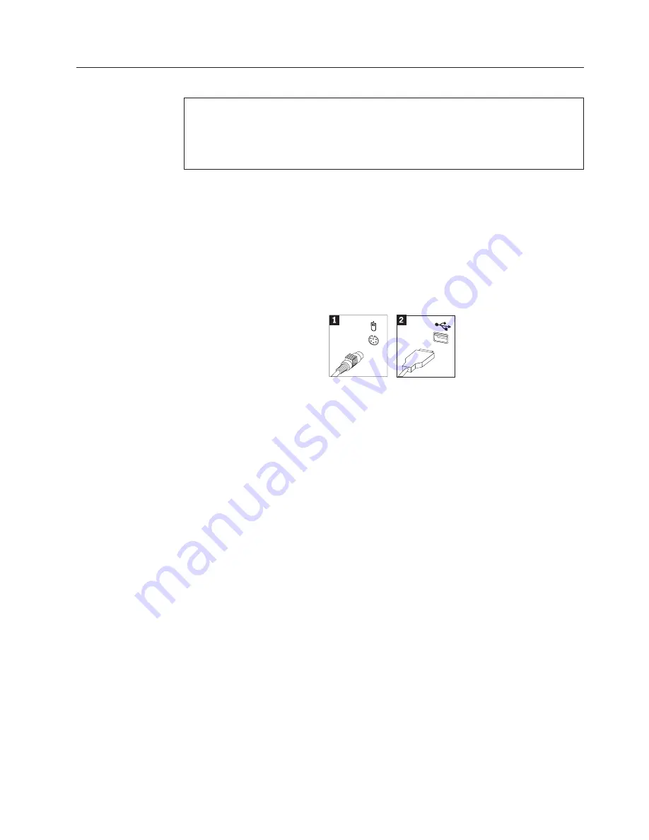
Your
mouse
might
be
connected
to
the
standard
mouse
connector
1
at
the
rear
of
the
computer
or
to
a
USB
connector
2
at
either
the
front
or
rear
of
the
computer.
Locate
the
connector
for
the
mouse.
4.
Disconnect
the
failing
mouse
cable
from
the
computer
and
connect
the
new
mouse
cable
to
the
same
connector.
5.
Go
to
“Completing
the
parts
replacement”
on
page
31.
Chapter
2.
Replacing
hardware
29