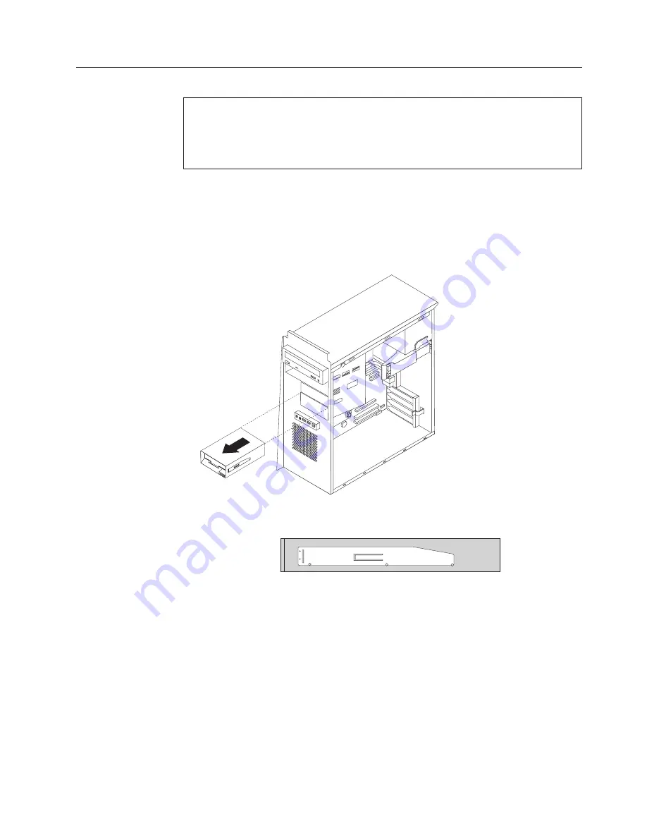
background image

Replacing


the


diskette


drive


Attention:


Do


not


open


your


computer


or


attempt


any


repair


before


reading


the


“Important


safety


information”


in


the


Quick


Reference


that


was


included


with


your


computer


or


in


the


Hardware


Maintenance


Manual


(HMM)


for


the


computer.


To


obtain


copies


of


the


Quick


Reference


or


HMM

,


go


to


http://www.ibm.com/pc/support/.


1.


Remove


the


computer


cover.


See


“Removing


the


cover”


on


page


5.


2.


Remove


the


front


bezel.


See


“Removing


and


replacing


the


front


bezel”


on


page


6.


3.


Disconnect


the


signal


and


power


cables


from


the


rear


of


the


diskette


drive.


4.


Release


the


drive


by


pressing


on


the


blue


retainer


lever


at


the


side


of


the


drive


and


sliding


it


outward


from


the


front


of


the


computer.


5.


Remove


the


retainer


bracket


from


the


failing


drive


and


install


it


on


the


new


drive.


6.


Install


the


diskette


drive


into


the


bay


until


it


snaps


into


position.


7.


Connect


the


signal


and


power


cables


to


the


drive.


8.


To


install


the


new


bezel,


align


the


tabs


on


the


bottom


of


the


bezel


with


the


corresponding


holes


in


the


chassis.


Pivot


the


bezel


until


it


snaps


into


position


at


the


top


of


the


chassis.


9.


Go


to


“Completing


the


parts


replacement”


on


page


31.


Chapter


2.


Replacing


hardware


27

Summary of Contents for ThinkCentre 9212

Page 1: ...ThinkCentre Hardware Replacement Guide Types 9212 9213...

Page 2: ......

Page 3: ...ThinkCentre Hardware Replacement Guide Types 9212 9213...

Page 4: ...n March 2005 Copyright International Business Machines Corporation 2005 All rights reserved US Government Users Restricted Rights Use duplication or disclosure restricted by GSA ADP Schedule Contract...

Page 5: ...on the system board 4 Chapter 2 Replacing hardware 5 Removing the cover 5 Removing and replacing the front bezel 6 Replacing the power supply 6 Replacing the system board assembly 10 Replacing the mic...

Page 6: ...iv Hardware Replacement Guide...

Page 7: ...on for replacing CRUs Do not open your computer or attempt any repair before reading the Important safety information in the Quick Reference that was included with your computer If you no longer have...

Page 8: ...lectricity to build up around you v Always handle parts and other computer components carefully Handle adapters memory modules system boards and microprocessors by the edges Never touch any exposed ci...

Page 9: ...e the cover see Removing the cover on page 5 Locating components The following illustration will help you locate the various components in your computer 1 Optical drive 2 Memory modules 3 Power supply...

Page 10: ...er This section shows the various external connectors on the computer to which you can attach external devices 1 3 9 4 1 IEEE 1394 connector 4 Microphone connector 2 USB connector 5 Headphone connecto...

Page 11: ...nnector 3 Power connector 13 PCI Express x16 adapter connector some models 4 Audio line in connector 14 PCI adapter connector 5 Audio line out connector 15 PCI adapter connector 6 Microphone connector...

Page 12: ...tor 2 Memory connector 4 13 PCI adapter connector 3 Memory connector 3 14 Serial connector COM 2 4 Memory connector 2 15 PCI Express x1 adapter connector 5 Memory connector 1 16 Clear CMOS Recovery ju...

Page 13: ...the computer cover 1 Remove any media diskettes CDs or tapes from the drives shut down your operating system and turn off all attached devices 2 Unplug all power cords from electrical outlets 3 Discon...

Page 14: ...snaps into position at the top of the chassis 4 Go to Completing the parts replacement on page 31 Replacing the power supply Attention Do not open your computer or attempt any repair before reading t...

Page 15: ...er 1 to the left and pull the blue handle 2 outward Pivot the hard disk drive outward to the fully open position as shown 4 Disconnect the power supply cables 1 and 2 connected to the system board Cha...

Page 16: ...that the screw holes in the power supply align with those in the chassis Note Use only the screws provided 8 Install and tighten the four screws at the rear of the chassis that secure the power suppl...

Page 17: ...11 Push the blue lever 1 and pivot the hard disk drive inward until it is latched into position 12 Go to Completing the parts replacement on page 31 Chapter 2 Replacing hardware 9...

Page 18: ...ake it easier to access the system board 3 Carefully note the location of all cable connections on the system board It will be necessary to reconnect them correctly after you install the new system bo...

Page 19: ...memory modules from the defective system board and install them in the same connector on the new system board See Replacing a memory module on page 19 Return here after installing the memory modules 1...

Page 20: ...seven screw holes and install the screws 14 Reinstall all adapter cards See Replacing a PCI adapter on page 20 15 Route the fan cable through the notch on the side of the air baffle Then reinstall th...

Page 21: ...or you will also receive a new heat sink and vacuum pen You must use the new heat sink with the new microprocessor If you use the old heat sink with the new microprocessor your computer might overheat...

Page 22: ...ng a defective system board you must reinstall the same heat sink Carefully place the heat sink on its side on a clean flat surface so the thermal material on the bottom of the heat sink does not touc...

Page 23: ...he microprocessor touch only the sides Notes a Take notice of the orientation of the notches 1 on the microprocessor This is important when reinstalling the microprocessor on the system board X X X X...

Page 24: ...microprocessor then completely remove the cover X X X X X X X X X 10 Position the microprocessor so that the notches on the microprocessor are aligned with the tabs in the microprocessor socket Import...

Page 25: ...d position and pivot the locking lever 2 to secure the microprocessor 1 in place Make sure the locking lever is engaged with the retainer tab when securing the microprocessor Note If you are replacing...

Page 26: ...re replacing the system board continue at step 12 on page 12 If you are replacing only the microprocessor continue at the next step 15 Route the fan cable through the notch on the side of the air baff...

Page 27: ...www ibm com pc support 1 Remove the computer cover See Removing the cover on page 5 2 Locate the memory connectors See Locating components on page 1 3 Open the retaining clips and lift the memory modu...

Page 28: ...ter To obtain copies of the Quick Reference or HMM go to http www ibm com pc support 1 Remove the computer cover See Removing the cover on page 5 2 Push the blue adapter latch as indicated and pivot i...

Page 29: ...5 Pivot the blue adapter latch to the closed position to secure the adapters 6 Go to Completing the parts replacement on page 31 Chapter 2 Replacing hardware 21...

Page 30: ...hard disk drive you will also receive a Product Recovery CD The Product Recovery CD will enable you to restore the contents of the hard disk drive to the same state as when the computer was originall...

Page 31: ...drive from the blue bracket by flexing the bracket 6 To install the new hard disk drive into the blue bracket flex the bracket and align the pins 1 through 4 on the bracket with the holes in the hard...

Page 32: ...signal cables to the new hard disk drive See Identifying parts on the system board on page 4 9 Press the blue tab 1 to pivot the drive into the computer Route the cables so that the hard disk drive ba...

Page 33: ...copies of the Quick Reference or HMM go to http www ibm com pc support 1 Remove the computer cover See Removing the cover on page 5 2 Disconnect the signal and power cables from the rear of the failin...

Page 34: ...Install the optical drive into the bay until it snaps into position 6 Connect the signal and power cables to the drive 7 Go to Completing the parts replacement on page 31 26 Hardware Replacement Guid...

Page 35: ...nect the signal and power cables from the rear of the diskette drive 4 Release the drive by pressing on the blue retainer lever at the side of the drive and sliding it outward from the front of the co...

Page 36: ...l attached devices 2 Unplug all power cords from electrical outlets 3 Locate the keyboard connector See Locating connectors on the rear of the computer on page 3 and Locating connectors on the front o...

Page 37: ...off all attached devices 2 Unplug all power cords from electrical outlets 3 Locate the mouse connector See Locating connectors on the rear of the computer on page 3 and Locating connectors on the fron...

Page 38: ...ver See Removing the cover on page 5 2 To locate the internal speaker see Locating components on page 1 3 Disconnect the speaker cable from the system board See Identifying parts on the system board o...

Page 39: ...p Utility in your Quick Reference To complete the installation 1 Ensure that all components have been reassembled correctly and that no tools or loose screws are left inside your computer See Locating...

Page 40: ...on the label of your computer you must update flash the BIOS to change the serial number and the machine type model To update flash the BIOS from a diskette do the following 1 Insert a system program...

Page 41: ......

Page 42: ...Part Number 39J7726 Printed in USA 1P P N 39J7726...

Reviews: