background image

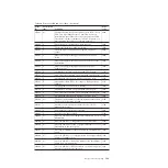
Table 26. Error event IDs and error codes (continued)

Event
ID

Notification
type

Condition

Error
code

009173

W

The FlashCopy feature has exceeded the amount that is
licensed.

3032

009174

W

The Metro Mirror or Global Mirror feature has exceeded
the amount that is licensed.

3032

009175

W

The usage for the thin-provisioned volume is not
licensed.

3033

009176

W

The value set for the virtualization feature capacity is not
valid.

3029

009177

E

A physical disk FlashCopy feature license is required.

3035

009178

E

A physical disk Metro Mirror and Global Mirror feature
license is required.

3036

009179

E

A virtualization feature license is required.

3025

009180

E

Automatic recovery of offline node failed.

1194

009181

W

Unable to send email to any of the configured email
servers.

3081

009182

W

The external virtualization feature license limit was
exceeded.

3032

009183

W

Unable to connect to LDAP server.

2251

009184

W

The LDAP configuration is not valid.

2250

010002

E

The node ran out of base event sources. As a result, the
node has stopped and exited the system.

2030

010003

W

The number of device logins has reduced.

1630

010006

E

A software error has occurred.

2030

010008

E

The block size is invalid, the capacity or LUN identity
has changed during the managed disk initialization.

1660

010010

E

The managed disk is excluded because of excessive
errors.

1310

010011

E

The remote port is excluded for a managed disk and
node.

1220

010012

E

The local port is excluded.

1210

010013

E

The login is excluded.

1230

010014

E

The local port is excluded.

1211

010017

E

A timeout has occurred as a result of excessive
processing time.

1340

010018

E

An error recovery procedure has occurred.

1370

010019

E

A managed disk I/O error has occurred.

1310

010020

E

The managed disk error count threshold has exceeded.

1310

010021

W

There are too many devices presented to the cluster
(system).

1200

010022

W

There are too many managed disks presented to the
cluster (system).

1200

010023

W

There are too many LUNs presented to a node.

1200

010024

W

There are too many drives presented to a cluster
(system).

1200

Chapter 9. Event reporting

121

||||

||||

Summary of Contents for Storwize V7000

Page 1: ...IBM Storwize V7000 Version 6 3 0 Troubleshooting Recovery and Maintenance Guide GC27 2291 02...

Page 2: ...he IBM Environmental Notices and User Guide on the documentation DVD This edition applies to the IBM Storwize V7000 Version 6 3 0 and to all subsequent releases and modifications until otherwise indic...

Page 3: ...m 29 Management GUI interface 29 When to use the management GUI 30 Accessing the management GUI 30 Service assistant interface 31 When to use the service assistant 31 Accessing the service assistant 3...

Page 4: ...enclosure 85 Replacing a power supply unit for an expansion enclosure 89 Replacing a battery in a power supply unit 93 Releasing the cable retention bracket 96 Replacing a 3 5 drive assembly or blank...

Page 5: ...SAS ports on the node canisters 13 18 LEDs on the node canisters 14 19 SAS ports and LEDs in rear of expansion enclosure 16 20 LEDs on the expansion canisters 17 21 LEDs on the power supply units of...

Page 6: ...vi Storwize V7000 Troubleshooting Recovery and Maintenance Guide...

Page 7: ...2 11 10 Gbps Ethernet port LEDs 13 12 SAS port LEDs on the node canister 13 13 Node canister LEDs 14 14 SAS port LEDs on the expansion canister 16 15 Expansion canister LEDs 17 16 Access information f...

Page 8: ...viii Storwize V7000 Troubleshooting Recovery and Maintenance Guide...

Page 9: ...e or minor personal injury C001 DANGER A danger notice indicates the presence of a hazard that has the potential of causing death or serious personal injury D002 2 Locate IBM Storwize V7000 Safety Not...

Page 10: ...x Storwize V7000 Troubleshooting Recovery and Maintenance Guide...

Page 11: ...0 Summary of changes for GC27 2291 02 Storwize V7000 Troubleshooting Recovery and Maintenance Guide The summary of changes provides a list of new and changed information since the last version of the...

Page 12: ...Boldface Text in boldface represents menu items Bold monospace Text in bold monospace represents command names Italics Text in italics is used to emphasize a word In command syntax it is used for var...

Page 13: ...s describes verifying your order becoming familiar with the hardware components and meeting environmental requirements The second chapter describes installing the hardware and attaching data cables an...

Page 14: ...u can use from the Storwize V7000 command line interface CLI GC27 2287 IBM Environmental Notices and User Guide This multilingual guide describes environmental policies to which IBM products adhere as...

Page 15: ...com storage support storwize v7000 Support for IBM System Storage and IBM TotalStorage products www ibm com storage support IBM Publications Center www ibm com e business linkweb publications servlet...

Page 16: ...of that page to identify the topic for which you have a comment v Send your comments by email to starpubs us ibm com Include the following information for this publication or use suitable replacements...

Page 17: ...losure models v Machine type and model 2076 112 which can hold up to 12 3 5 inch drives v Machine type and model 2076 124 which can hold up to 24 2 5 inch drives v Machine type and model 2076 312 whic...

Page 18: ...enclosure The 12 drives are mounted in four columns with three rows The 24 drives are mounted vertically in one row Note The drive slots cannot be empty A drive assembly or blank carrier must be in ea...

Page 19: ...the LED is flashing the drive is ready and there is activity Green Fault Indicates a fault or identifies a drive v If the LED is on a fault exists on the drive v If the LED is off no known fault exist...

Page 20: ...3 Right end cap Figure 6 shows the indicators on the front of the enclosure end cap The left enclosure end caps for both enclosures are identical and contain only indicators The left enclosure end cap...

Page 21: ...losure Two canisters are located in the middle of each enclosure The power supply units are located on the left and right of the canisters The left slot is power supply 1 1 and the right slot is power...

Page 22: ...t to be operational If the power switches are turned off or the main power is removed the integrated batteries temporarily continue to supply power to the node canisters As a result the canisters can...

Page 23: ...using the LEDs on page 49 for help in diagnosing a particular failure Power supply unit for the expansion enclosure The expansion enclosure contains two power supply units The two power supply units i...

Page 24: ...of the expansion enclosure Name Color Symbol ac power failure Amber Power supply OK Green Fan failure Amber dc power failure Amber See Procedure Understanding the system status using the LEDs on page...

Page 25: ...two green LEDs associated with each port the speed LED and the link activity LED These LEDs are in the shape of a triangle The LEDs are located in between the two rows of the ports as shown in Figure...

Page 26: ...ng Active high speed 8 Gbps Fibre Channel port numbers and worldwide port names Fibre Channel ports are identified by their physical port number and by a worldwide port name WWPN The physical port num...

Page 27: ...nclosure models have two 1 Gbps Ethernet ports per node canister Model 2076 312 and model 2076 324 also have two 10 Gbps Ethernet ports per node canister For the 1 Gbps support the Ethernet ports are...

Page 28: ...f upper canister The LED is flashing when there is activity on the link otherwise the LED is off Yellow Figure 16 shows the location of the 10 Gbps Ethernet ports Table 11 on page 13 provides a descri...

Page 29: ...port provides four data channels Note The reference to the left and right locations applies to canister 1 which is the upper canister The port locations are inverted for canister 2 which is the lower...

Page 30: ...node is active that is it is an active member of a clustered system When the node is active do not remove it v The off state indicates there is no power to the canister or the canister is in standby m...

Page 31: ...available and that the canister is in standby mode The main processor or processors are off and only the service processor is active v The fast flashing 2 Hz indicates that the canister is running the...

Page 32: ...the status of one data channel within the port The data channel is shown with the LED Table 14 SAS port LEDs on the expansion canister LED state Description Off No link is connected Flashing The link...

Page 33: ...ED is flashing there is a vital product data VPD error Green Fault Indicates if a fault is present and identifies the canister v If the LED is on a fault exists v If the LED is off no fault exists v I...

Page 34: ...18 Storwize V7000 Troubleshooting Recovery and Maintenance Guide...

Page 35: ...closures is used only in certain circumstances The service IP address connects to a node canister in the control enclosure Access to the address is sometimes required if the canister has a fault that...

Page 36: ...ns when a new event is reported Select the type of event that you want to be notified about For example restrict notifications to just events that require immediate action Several event notification m...

Page 37: ...members and drives that are spares The spare drives are used automatically if a member drive fails If you have sufficient spare drives you do not have to replace them immediately when they fail Howev...

Page 38: ...ifications Subscribe to support notifications so that you are aware of best practices and issues that might affect your system Subscribe to support notifications by visiting the IBM support page on th...

Page 39: ...drive until approximately 10 seconds after the loss of ac power is first detected If the power is restored within this period the system continues to operate This loss in power is called a brown out...

Page 40: ...insufficient to perform a saving of the critical data if the ac power fails Data protection cannot be guaranteed in this case The nodes save the critical data by using the ac power and enter service...

Page 41: ...failures without a sufficient time interval in between the ac failures to complete battery conditioning then neither battery is considered when calculating whether there is sufficient charge to prote...

Page 42: ...26 Storwize V7000 Troubleshooting Recovery and Maintenance Guide...

Page 43: ...these cases the migrated volume or the replicated volume returns a medium error to the host when the logical block address on the original volume is read The system maintains tables of bad blocks to r...

Page 44: ...bad block from being propagated when the volume is replicated or migrated It is possible however for the bad block to be on part of the volume that is not used by the application For example it can be...

Page 45: ...problems You use the management GUI to manage and service your system The Monitoring Events panel provides access to problems that must be fixed and maintenance procedures that step you through the p...

Page 46: ...tion about the problem They suggest actions to take and step you through the actions that automatically manage the system where necessary Finally they check that the problem is resolved If there is an...

Page 47: ...e The node canister cannot be active as part of a system while it is in service state Attention Perform service actions on node canisters only when directed to do so by the fix procedures If used inap...

Page 48: ...at www ibm com storage support storwize v7000 To start the application perform the following steps 1 Start a supported web browser and point your web browser to serviceaddress service for the node can...

Page 49: ...cluster system CLI Follow the steps that are described in the Command line interface topic in the Reference section of the Storwize V7000 Information Center to initialize and use a CLI session Service...

Page 50: ...is specified in the file When the command completes a file called satask_result html is written to the root directory of the USB key If this file does not exist it is created If it exists the data is...

Page 51: ...By using the initialization tool you can set the USB key to run one of the following tasks v Create a new system v Reset the superuser password v Set or reset the service IP address on the node canis...

Page 52: ...the command is run on the lower canister the default value is 192 168 70 122 subnet mask 255 255 255 0 If the node canister is active in a system the superuser password for the system is reset otherwi...

Page 53: ...node canister and to write the output to a USB key Syntax satask snap options Parameters options Optional Specifies which diagnostic information to collect Description This command moves a snap file t...

Page 54: ...em gw_6 Required The IPv6 gateway for Ethernet port 1 on the system prefix_6 Required The IPv6 prefix for Ethernet port 1 on the system name Optional The name of the new system Description This comman...

Page 55: ...system remove hardware components only when directed to do so by the fix procedures Failure to follow the procedures can result in loss of access to data or loss of data Follow the fix procedures whe...

Page 56: ...in the order shown to resolve the most serious issues first Often other alerts are fixed automatically because they were the result of a more serious issue After all the alerts are fixed go to Proced...

Page 57: ...ection v If you have just created the clustered system using the USB key or service assistant and entered a management IP address that is not accessible you can safely delete the system and perform th...

Page 58: ...ormation using the service assistant on page 48 or Procedure Getting node canister and system information using a USB key on page 49 If the node is in service state fix the reported node errors For mo...

Page 59: ...s on page 49 v The service assistant is configured on Ethernet port 1 of a node canister Verify that an Ethernet cable is connected to this port and to an active port on your Ethernet network See Proc...

Page 60: ...t operate in an expansion enclosure An expansion canister cannot operate in a control enclosure v After the node has been used in a clustered system the node canister has saved information that can id...

Page 61: ...nsion enclosure At least one power supply unit must be on with no faults shown At least one canister must be active with no fault LED on and all the serial attached SCSI SAS port 1 LEDs must be on For...

Page 62: ...this problem during initial setup or when running commands if you are using your own USB key rather than the USB key that was packaged with your order If you encounter this situation verify the follow...

Page 63: ...ferences between the enclosures you must be able to distinguish between the control enclosures and the expansion enclosures when you service the system Be aware of the following differences v The mode...

Page 64: ...loss of access to data or loss of data Procedure Checking the status of your system Use this procedure to verify the status of objects in your system using the management GUI If the status of the obj...

Page 65: ...a USB key Use any USB key with a FAT32 file system a EXT2 file system or a EXT3 file system on its first partition 1 Ensure that the USB key does not contain a file named satask txt in the root direct...

Page 66: ...and node canisters Your control enclosure is operational if you can manage the system using the management GUI You might also want to view the status of the individual power supply units batteries or...

Page 67: ...power supply unit If failure is still present replace the enclosure chassis Off Off Off Off No ac power to the enclosure Turn on power Off Off Off On The ac power is on but power supply unit is not se...

Page 68: ...urn on both switches If this action does not resolve the problem remove both canisters slightly and then push the canisters back in Off Flashing Flashing Flashing Firmware is downloading No actions Do...

Page 69: ...r 3 If the power LED is on consider the states of the clustered system status and fault LEDs Table 20 System status and fault LEDs System status LED Fault LED Status Action Off Off Code is not active...

Page 70: ...tem Several problems can exist hardware problem a problem with the environment or its location or problems with the code or data on the canister Follow the procedure to fix the node errors Go to Proce...

Page 71: ...re returned for each port Information is returned that identifies whether the node is the configuration node and if any node errors were reported v Examine the LEDs of the Ethernet ports For the statu...

Page 72: ...installation Attention This procedure makes all the volume data that you have on your system inaccessible You cannot recover the data This procedure affects all volumes that are managed by your system...

Page 73: ...actions for each error are listed with the error code Go to Error code range on page 130 Procedure Changing the service IP address of a node canister This procedure identifies many methods that you c...

Page 74: ...ggg ggg ggg ggg mask mmm mmm mmm mmm where you must replace aaa aaa aaa aaa with the management IP address ggg ggg ggg ggg with the network gateway address and mmm mmm mmm mmm with the subnet mask add...

Page 75: ...dress of the upper node canister in your control enclosure 192 168 70 121 subnet mask 255 255 255 0 2 Log on with the superuser password The default password is passw0rd If you are unable to connect s...

Page 76: ...superuser password The default password is passw0rd 6 After the action completes disconnect your personal computer and reconnect the node canister to the Ethernet network 7 Set the service address of...

Page 77: ...shing which indicates that the shutdown operation has completed The following figure shows the LEDs on the node canisters The power LED is the LED on the left when the canister is top side up 4 Using...

Page 78: ...ou want to reinstall the software on is the current node Go to Accessing the service assistant on page 32 2 Select Reinstall Software from the navigation 3 Select Rescue from another node SAN problem...

Page 79: ...you must provide a suitable replacement Removing the wrong SFP transceiver could result in loss of data access 4 Perform the Fibre Channel switch service procedures for a failing Fibre Channel link Th...

Page 80: ...64 Storwize V7000 Troubleshooting Recovery and Maintenance Guide...

Page 81: ...anisters must be at the same level of software that the storage system had before the system failure If any node canisters were modified or replaced use the service assistant to verify the levels of s...

Page 82: ...its configuration data If any nodes report anything other than these error codes do not perform a recovery You can encounter situations where non configuration nodes report other node errors such as...

Page 83: ...still present restart the node by clicking Restart Node from the service assistant Note If after resolving all these scenarios half or greater than half of the nodes are reporting node error 578 it is...

Page 84: ...n configured you must assign an IP address using the initialization tool 2 Log on to the service assistant 3 Select Manage System 4 Click Remove System Data 5 Confirm that you want to remove the syste...

Page 85: ...nisters If you do not know the IP address or if it has not been configured you must assign an IP address using the initialization tool 2 Log on to the service assistant 3 Select Recover System from th...

Page 86: ...ppings and Metro Mirror or Global Mirror relationships that use the volumes What to check after running the system recovery Several tasks must be performed before you use the volumes Differences to be...

Page 87: ...ps and managed disks MDisks do not restore correctly if the ID of the object is different from what is recorded in the current configuration data file v All other objects with default names are rename...

Page 88: ...renamed during the restore process The new names appear in the format name_r where name is the name of the object in your system The backup feature of the svcconfig CLI command is designed to back up...

Page 89: ...ollowing table describes the three files that are created by the backup process File name Description svc config backup xml This file that contains your configuration data svc config backup sh This fi...

Page 90: ...For directions on the recover procedure see Recover system procedure on page 65 This configuration restore procedure is designed to restore information about your configuration such as volumes local...

Page 91: ...other changes on the panel d Click Modify to make the changes 3 Use the initialization tool that is available on the USB key to initialize the system with the IP address Go to Using the initialization...

Page 92: ...tings Support b Click Show full log listing c Find the file name that begins with svc config cron xml d Double click the file to download the file to your computer 10 Issue the following CLI command t...

Page 93: ...e recovery process the current license settings do not match the previous license settings The recovery process continues normally and you can enter the correct license settings in the management GUI...

Page 94: ...uster_ip is the IP address or DNS name of the clustered system from which you want to delete the configuration 2 Issue the following CLI command to erase all of the files that are stored in the tmp di...

Page 95: ...n you are replacing the hardware components that are located in the back of the system that you do not inadvertently disturb or remove any cables that you are not instructed to remove Preparing to rem...

Page 96: ...t you know which canister to replace Go to Procedure Identifying which enclosure or canister to service on page 47 3 Record which data cables are plugged into the specific ports of the node canister T...

Page 97: ...powered on and performing I O operations go to the management GUI and follow the fix procedures Performing the replacement actions without the assistance of the fix procedures can result in loss of da...

Page 98: ...re plugged into the specific ports of the expansion canister The cables must be inserted back into the same ports after the replacement is complete otherwise the system cannot function properly 3 Disc...

Page 99: ...dures are intended to be used only when your system is not up and running and performing I O operations Unless your system is offline go to the management GUI and follow the fix procedures Be careful...

Page 100: ...do not pull on the optical cables 3 Remove the SFP transceiver There are a number of different handling or locking mechanisms that are used on the SFP transceivers Some SFP transceivers might have a p...

Page 101: ...se rotation according to the system rating plate v Connect any equipment that will be attached to this product to properly wired outlets v When possible use one hand only to connect or disconnect sign...

Page 102: ...the backup battery might not be sufficient enough within the partner power supply unit to continue operations without causing a loss of access to the data Wait until the partner battery is 100 charged...

Page 103: ...to the enclosure with the handle pointing towards the center of the enclosure Insert the unit in the same orientation as the one that you removed svc00633 Figure 29 Directions for lifting the handle o...

Page 104: ...andle until the locking catch clicks into place 9 Reattach the power cable and cable retention bracket 10 Turn on the power switch to the power supply unit If required return the power supply Follow a...

Page 105: ...hase rotation according to the system rating plate v Connect any equipment that will be attached to this product to properly wired outlets v When possible use one hand only to connect or disconnect si...

Page 106: ...components that are located in the back of the system that you do not inadvertently disturb or remove any cables that you are not instructed to remove Ensure that you are aware of the procedures for h...

Page 107: ...to the enclosure with the handle pointing towards the center of the enclosure Insert the unit in the same orientation as the one that you removed svc00633 Figure 31 Directions for lifting the handle o...

Page 108: ...ndle until the locking catch clicks into place 9 Reattach the power cable and cable retention bracket 10 Turn on the power switch to the power supply unit If required return the power supply Follow al...

Page 109: ...uipment that will be attached to this product to properly wired outlets v When possible use one hand only to connect or disconnect signal cables v Never turn on any equipment when there is evidence of...

Page 110: ...ng and performing I O operations Unless your system is offline go to the management GUI and follow the fix procedures Be careful when you are replacing the hardware components that are located in the...

Page 111: ...ement battery has protective end caps that must be removed prior to use a Remove the battery from the packaging b Remove the end caps c Attach the end caps to both ends of the battery that you removed...

Page 112: ...ug in To release a cable retention bracket perform these steps 1 Unlock the cable retention bracket that is around the end of the power cord 2 Pull the lever next to the black plastic loop slightly to...

Page 113: ...drive back into the slot until the handle starts to move 6 Finish inserting the drive by closing the handle until the locking catch clicks into place svc00612 Figure 34 Unlocking the 3 5 drive svc0061...

Page 114: ...ta or access to data Attention Do not leave a drive slot empty Do not remove a drive or drive assembly before you have a replacement available To replace the drive assembly or blank carrier perform th...

Page 115: ...ide of the drive assemblies and gently pushing it on Replacing a SAS cable This topic describes how to replace a SAS cable Be careful when you are replacing the hardware components that are located in...

Page 116: ...to replace a control enclosure chassis Note Ensure that you know the type of enclosure chassis that you are replacing The procedures for replacing a control enclosure chassis are different from those...

Page 117: ...lets v When possible use one hand only to connect or disconnect signal cables v Never turn on any equipment when there is evidence of fire water or structural damage v Disconnect the attached power co...

Page 118: ...1 and WWNN 2 from the enclosure column v If you are replacing the enclosure because neither node canister can start retrieve this information after you have completed the replacement a Start the servi...

Page 119: ...because it is used again 14 Remove the clamping screws that attached the enclosure to the rack cabinet 15 Remove the enclosure chassis from the front of the rack cabinet and take the chassis to a wor...

Page 120: ...not have a full set of values contact IBM support After you modify the configuration the node attempts to restart Note There are situations where the canisters restart and report critical node error...

Page 121: ...in the tree view and verify that it is now online and managed 31 Change the enclosure ID of the replaced enclosure to that of the original enclosure From the Enclosure ID field select the ID value of...

Page 122: ...possible use one hand only to connect or disconnect signal cables v Never turn on any equipment when there is evidence of fire water or structural damage v Disconnect the attached power cords telecomm...

Page 123: ...activity to the enclosure which includes host access FlashCopy Metro Mirror and Global Mirror access 2 Turn off the power to the enclosure by using the switches on the power supply units 3 Record whic...

Page 124: ...f the enclosure 21 Turn on the power to the enclosure by using the switches on the power supply units The system records an error that indicates that an enclosure FRU replacement was detected Go to th...

Page 125: ...the upper mounting hole between the rail location pins 15 Tighten the screw to secure the rail to the rack from the back side 16 Repeat the steps to secure the opposite rail to the rack cabinet Storwi...

Page 126: ...k 39M5130 All Customer replaced 2 8 m power cord South Africa 39M5144 All Customer replaced 2 8 m power cord Switzerland 39M5158 All Customer replaced 2 8 m power cord Chile 39M5165 All Customer repla...

Page 127: ...lank 2 5 carrier 85Y5893 124 224 324 Customer replaced Blank 3 5 carrier 85Y5894 112 212 312 Customer replaced Fibre Channel shortwave small form factor pluggable SFP 85Y5958 112 124 312 324 Customer...

Page 128: ...112 Storwize V7000 Troubleshooting Recovery and Maintenance Guide...

Page 129: ...sages v An alert is logged when the event requires some action Some alerts have an associated error code that defines the service action that is required The service actions are automated through the...

Page 130: ...t uniquely identifies the instance of the object Fixed When an alert is shown for an error condition it indicates if the reason for the event was resolved In many cases the system automatically marks...

Page 131: ...problem or unexpected condition with the Storwize V7000 Always immediately investigate this type of notification to determine the effect that it might have on your operation and make any necessary cor...

Page 132: ...ational events are recorded in the event log and depending on the configuration can be notified through email SNMP or syslog Informational events can be either notification type I information or notif...

Page 133: ...licensed 980503 W The Metro Mirror or Global Mirror feature is close to the limit that is licensed 980504 I The limit was reached for the external virtualization feature 981002 I Fibre Channel discove...

Page 134: ...ng pinned in a virtual disk working set 984002 I All customer data in a virtual disk working set is now unpinned 984003 W The volume working set cache mode is in the process of changing to synchronous...

Page 135: ...oned volume copy repair has started 986031 I A thin provisioned volume copy repair is successful 986032 I A thin provisioned volume copy validation is started 986033 I A thin provisioned volume copy v...

Page 136: ...procedure that must be followed Each event ID that requires service has an associated error code Table 26 lists the event IDs and corresponding error codes Table 26 Error event IDs and error codes Ev...

Page 137: ...010002 E The node ran out of base event sources As a result the node has stopped and exited the system 2030 010003 W The number of device logins has reduced 1630 010006 E A software error has occurred...

Page 138: ...42 E The controller system device is only connected to the cluster system nodes through a single target port 1627 010043 E The controller system device is only connected to the cluster system nodes th...

Page 139: ...nalysis PFA errors 1680 010080 E The drive is reporting too many errors 1680 010081 E The drive format is corrupted 1206 010082 E The block size for the drive was incorrect 1206 010083 E The drive is...

Page 140: ...ans have failed 1124 045002 E A fan is operating outside the expected range 1126 045003 E There was a fan status communications failure 1126 045004 E The power supply unit is not installed 1128 045005...

Page 141: ...7 E The SAS network has too many errors 1048 045038 E The SAS network has too many errors 1048 045040 W The firmware update for the enclosure component has failed 3015 045041 W More than one initiator...

Page 142: ...0 E There are too many self initiated resets on the enclosure 1048 045082 E The slots are powered off 1048 050001 W The relationship is stopped because of a clustered system or complete I O group fail...

Page 143: ...while the system is starting 1182 070550 E Cannot form cluster system due to lack of resources 1192 070556 E Duplicate WWNN detected on the SAN 1192 070558 E A node is unable to communicate with othe...

Page 144: ...attery available to start the node One battery is charging 1192 071673 E There is not enough battery available to start the node No batteries are charging 1192 071690 W Node held in service state 1189...

Page 145: ...corrupt on high speed SAS adapter 1121 076511 E A high speed SAS controller is missing 1032 076512 E Degraded PCIe lanes on a high speed SAS adapter 1032 076513 E A PCI bus error occurred on a high s...

Page 146: ...s in the starting state The range of errors that are reserved for critical errors are 500 699 Noncritical errors A noncritical error code is logged when there is a hardware or software failure that is...

Page 147: ...er response Follow troubleshooting procedures to relocate the nodes to the correct location 1 Review the saved location information of the node canister and the status of the other node canister in th...

Page 148: ...canister in the enclosure the partner canister The correct node canister is the one that comes from the enclosure chassis that is being replaced The drives now in this enclosure should also come from...

Page 149: ...the node canister It will then join the cluster 3 If this is not the node canister that you intended to use follow the hardware remove and replace canister procedure to replace the node canister with...

Page 150: ...ve quorum disk or drive The node needs to be able to connect to a majority of the resources before that group will form an online cluster This prevents the cluster splitting into two or more active pa...

Page 151: ...closure chassis that was recently replaced or had its WWNN changed incorrectly Also consider how the SAN is zoned when making your decision 3 Determine the correct WWNN for the node with the incorrect...

Page 152: ...led User response If the other node canister is operational run node rescue Otherwise install new software using the service assistant Node rescue failures or the repeated return of this node error af...

Page 153: ...so both node canisters report this error The service assistant shows the estimated start time and the battery status in the node canister hardware details Possible Cause FRUs or other v None User res...

Page 154: ...en use the management GUI to resolve the problem 3 Use a USB key to get the status of the node and check whether it is the configuration node If the node showing this error is the configuration node u...

Page 155: ...ch you want to connect are visible to the node that is reporting the error Ensure that no more than 1024 exist 878 Attempting recovery after loss of state data Explanation During startup the node was...

Page 156: ...140 Storwize V7000 Troubleshooting Recovery and Maintenance Guide...

Page 157: ...I login panel You can use this option to navigate to all the panels without manually typing the web addresses v To go to the next frame press Ctrl Tab v To move to the previous frame press Shift Ctrl...

Page 158: ...ype your edit and press Enter to issue the change command Accessing the publications You can find the HTML version of the IBM Storwize V7000 information at the following website publib boulder ibm com...

Page 159: ...quiries in writing to Intellectual Property Licensing Legal and Intellectual Property Law IBM Japan Ltd 1623 14 Shimotsuruma Yamato shi Kanagawa 242 8502 Japan The following paragraph does not apply t...

Page 160: ...this document should verify the applicable data for their specific environment Information concerning non IBM products was obtained from the suppliers of those products their published announcements...

Page 161: ...ies in the United States and other countries Linux is a registered trademark of Linus Torvalds in the United States other countries or both Microsoft Windows Windows NT and the Windows logo are tradem...

Page 162: ...Avis de conformit la r glementation d Industrie Canada Cet appareil num rique de la classe A est conforme la norme NMB 003 du Canada Australia and New Zealand Class A Statement Attention This is a Cl...

Page 163: ...em Warnhinweis versehen werden Warnung Dieses ist eine Einrichtung der Klasse A Diese Einrichtung kann im Wohnbereich Funk St rungen verursachen in diesem Fall kann vom Betreiber verlangt werden angem...

Page 164: ...duct has been designed and built to comply with IEC Standard 950 United Kingdom telecommunications requirements This apparatus is manufactured to the International Safety Standard EN60950 and as such...

Page 165: ...mmunity contact IBM Technical Regulations Pascalstr 100 Stuttgart Germany 70569 Tele 0049 0 711 785 1176 Fax 0049 0 711 785 1283 Email mailto tjahn de ibm com Taiwan Contact Information This topic con...

Page 166: ...150 Storwize V7000 Troubleshooting Recovery and Maintenance Guide...

Page 167: ...ng with service assistant 59 with USB key 58 restore 70 clustered systems error codes 130 recovery codes 130 restore 66 T3 recovery 66 codes node error critical 130 noncritical 130 commands apply soft...

Page 168: ...dicators end cap 4 information center xii informational events 116 initialization tool interface 34 using 35 initializing clustered system with USB key 58 clustered systems with service assistant 59 I...

Page 169: ...reset superuser password 35 resetting superuser password 47 restore system 65 70 S safety notices ix sound pressure ix SAN storage area network problem determination 62 SAS ports 13 16 SAS cable repla...

Page 170: ...gement GUI 29 service assistant 31 USB key 34 V VDisks volumes recovering from offline using CLI 70 viewing event log 113 node canister status 48 49 system status 48 49 volumes VDisks recovering from...

Page 171: ......

Page 172: ...Printed in USA GC27 2291 02...

Reviews: