background image

Table 31. Physical characteristics of the expansion enclosures
Enclosure

Height

Width

Depth

Maximum weight

Drive ready

(without

drives)

Fully

configured

(with drives)

2077/2078-12F,

2077/2078-24F, or

2077/2078-AFF

87 mm (3.46

in.)

483 mm

(19.0 in.)

556 mm (21.9

in.)

16.7 kg (36.8

lb)

25.0 kg (55.1

lb)

2077-92F, 2077-A9F

2078-92F, 2078-A9F

222.2 mm

(8.75 in.)

483 mm

(19.0 in.)

968 mm (38.1

in.)

67 kg (147.7

lb)

135 kg (297

lb)

Attention: To avoid potential equipment damage during transport and subsequent loss of data,

see Procedure: Transporting a 5U 92-drive expansion enclosure. The procedure describes what to

do for the following situations.
• When you are powering off a 92F, 92G, or an A9F 5U expansion enclosure because you intend to

transport it to another location

• When you intend to move a rack that contains a 92F, 92G, or an A9F 5U expansion enclosure
The procedure describes how to remove each drive from the 5U enclosure and transport the

enclosure. Removing the drives prevents damage to the drives and makes the lighter enclosure

easier to move.
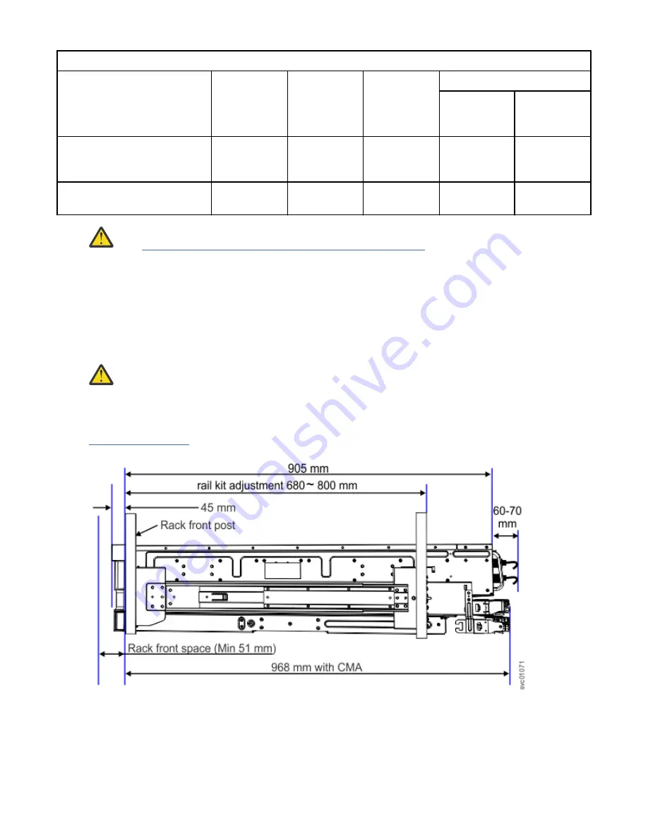
Warning: Some racks will not provide sufficient space to close the rear door. 2077-92F, 2077-A9F

and 2078-92F, 2078-A9F model enclosures need 968 mm from the rack front post to the back of

the cable management arm (CMA). In addition, allow 905 mm from the front post to the back of

the enclosure. To allow space for the power cables, provide 60 - 70 mm from the back of the

enclosure.

Figure 86 on page 93 shows the rack space requirements for the 5U ( 2077/2078-24F , 2077-92F,

2077-A9F and 2078-92F, 2078-A9F ) expansion enclosures.

Figure 86. Rack space requirements for the 5U expansion enclosures

The following table shows the rack space requirements for the expansion enclosures in tabular form.

Appendix D. SAS expansion enclosure requirements  93

Summary of Contents for Storwize V5100 Series

Page 1: ...IBM Storwize V5100 Quick Installation Guide for MTM 2078 424 2078 12F 2078 24F 2078 92F and 2078 U5B IBM...

Page 2: ...i The information in the IBM Environmental Notices and User Guide provided on a DVD This edition applies to version 8 release 3 modification 1 and to all subsequent modifications until otherwise indic...

Page 3: ...ew enclosure location guidelines 6 Chapter 2 Installing the system hardware 9 Installation overview 9 Unpacking the control enclosure 10 Installing support rails for the control enclosure 11 Installin...

Page 4: ...71 Initializing the system with the technician port 73 Completing the initial system setup customer task 74 Verify and update the system firmware and software customer task 76 Chapter 5 Adding an exp...

Page 5: ...emoving enclosure end caps 14 10 Inserting the enclosure 15 11 Securing the front of the enclosure 15 12 Tray containing expansion enclosure parts 16 13 Packaging materials 17 14 Packaging for fascia...

Page 6: ...losure 36 35 Correct drive installation 36 36 Incorrect drive installation 36 37 Replace the drive 37 38 Aligning the top cover 38 39 Replacing the top cover 38 40 Locking the top cover 38 41 Example...

Page 7: ...he enclosure 47 59 Features on the rear of the 5U expansion enclosure 48 60 LEDs on the front of the expansion enclosure 49 61 LEDs on the front of a power supply unit 50 62 LEDs on a drive assembly 5...

Page 8: ...e hinge brackets 67 79 Removing enclosure end caps 68 80 Inserting the enclosure 68 81 Reinstalling enclosure end caps 69 82 Expansion enclosure LEDs 69 83 Technician ports 74 84 Rack space requiremen...

Page 9: ...weight as FRUs are installed 24 11 Examples of supported SAS chain combinations 45 12 Display panel LEDs 49 13 Power supply unit LEDs 50 14 LED indicators on drives 51 15 LED indicators on secondary...

Page 10: ...requirements 92 31 Physical characteristics of the expansion enclosures 93 32 Rack space requirements for the 5U expansion enclosures 94 33 Clearances 94 34 Drive specifications 94 35 Acoustical spec...

Page 11: ...uding all Amendments under the Low Voltage Directive UL CSA North America bi national harmonized and marked per accredited NRTL agency listings and other such derivative certifications according to co...

Page 12: ...xii Storwize V5100 Quick Installation Guide for MTM 2078 424 2078 12F 2078 24F 2078 92F and 2078 U5B...

Page 13: ...ch for Storwize V5100 c Click the documentation link Safety notices and labels Review the safety notices and safety information labels before you use this product To view a PDF file you need Adobe Acr...

Page 14: ...f causing death or serious personal injury D002 CAUTION A caution notice indicates the presence of a hazard that has the potential of causing moderate or minor personal injury C001 2 After you downloa...

Page 15: ...abilizer brake function before each use Do not over force moving or rolling the LIFT TOOL with stabilizer brake engaged Do not raise lower or slide platform load shelf unless stabilizer brake pedal ja...

Page 16: ...njury C048 part 2 of 2 CAUTION Removing components from the upper positions in the rack cabinet improves rack stability during a relocation Follow these general guidelines whenever you relocate a popu...

Page 17: ...ng an electrical storm The product might be equipped with multiple power cords To remove all hazardous voltages disconnect all power cords Connect all power cords to a properly wired and grounded elec...

Page 18: ...th R010 Special caution and safety notices This information describes special safety notices that apply to the system These notices are in addition to the standard safety notices that are supplied the...

Page 19: ...around you Handle the device carefully holding it by its edges or frame Do not touch solder joints pins or exposed printed circuitry Do not leave the device where others can handle and possibly damage...

Page 20: ...xx Storwize V5100 Quick Installation Guide for MTM 2078 424 2078 12F 2078 24F 2078 92F and 2078 U5B...

Page 21: ...ntains all of the information that is required to install configure and manage the system The information collection in the IBM Knowledge Center is updated between product releases to provide the most...

Page 22: ...support Technical support for IBM storage products www ibm com support IBM Electronic Support registration www 01 ibm com support electronicsupport Sending your comments Your feedback is important in...

Page 23: ...shooting information in your system documentation The troubleshooting section of IBM Knowledge Center contains procedures to help you diagnose problems Write down the machine type and model MTM and th...

Page 24: ...xxiv Storwize V5100 Quick Installation Guide for MTM 2078 424 2078 12F 2078 24F 2078 92F and 2078 U5B...

Page 25: ...t if mishandled D006 The following general precautions should be observed even though the power on steps differ slightly from the directions that you will follow for this product DANGER When working o...

Page 26: ...en your shipment you must verify the contents against the packing slip In each box locate the packing slip Verify that the items that are listed in the packing slip match what is in the box and that a...

Page 27: ...total memory option and adds 6 x 32 GB DIMMs __ From 0 1 of the following host interface adapter options for the two available card slots Four port 32 Gbps Fibre Channel with four small form factor pl...

Page 28: ...is important to remember this orientation when you are installing adapters and cables Figure 1 Label showing the orientation of the node canisters and PSUs For example Figure 2 on page 4 shows the to...

Page 29: ...a control enclosure At the rear end of the control enclosure support rail the top edge curves over to capture the top edge of an inserted control enclosure This prevents the installed control enclosur...

Page 30: ...stall a system you must verify that adequate space in a suitable rack is available You must also ensure that the requirements for power and environmental conditions are met The quick installation guid...

Page 31: ...e For more information see the following chapter Each system can consist of up to two control enclosures Each control enclosure can be connected to up to 20 expansion enclosures two SAS chains of up t...

Page 32: ...8 Storwize V5100 Quick Installation Guide for MTM 2078 424 2078 12F 2078 24F 2078 92F and 2078 U5B...

Page 33: ...omplete the cabling Initial setup tasks that you must complete After the hardware is installed connect a laptop computer to the technician port of one of the node canisters in the control enclosure Th...

Page 34: ...upply units PSUs A combination of 24 drives and drive blanks The number of drives and drive blanks varies according to the number of drives that were specified in the product order For example if 12 d...

Page 35: ...replacing a node canister in the control enclosure in IBM Knowledge Center 12 Record the serial number on the release handle of each node canister then set the canisters aside Item Upper Node Caniste...

Page 36: ...rail mounting bracket pin 2 Lower rail mounting bracket pin 3 Rack mounting screw hole 3 Ensure that the appropriate bracket pins are installed in the front and rear bracket of each rail Each rail co...

Page 37: ...n the inside of the rack cabinet 6 On the rear of the rail press the two bracket pins into the holes in the rack flanges 7 Close the rear hinge bracket to secure the rail to the rack cabinet flange Se...

Page 38: ...closure end caps by grasping the handle and pulling the bottom of the end cap free then clearing the tab on the top of the enclosure See Figure 9 on page 14 Figure 9 Removing enclosure end caps 2 Alig...

Page 39: ...op of the end cap over the tab on the flange c Rotate the end cap down until it snaps into place d Ensure that the inside surface of the end cap is flush with the flange Unpacking an optional 5U expan...

Page 40: ...ins the front fascia 1U and 4U pieces the cable management arm CMA and the slide rail kit Figure 12 on page 16 shows how the enclosure is packaged for shipment Figure 12 Tray containing expansion encl...

Page 41: ...at bed lift Keep the remaining foam block protectors attached to the enclosure 5 Remove the support rail kit from the box in which it was shipped 1 as shown in Figure 12 on page 16 6 Remove the 4U and...

Page 42: ...he end of each notice for example D005 to find the matching translated notice in IBM Systems Safety Notices DANGER DANGER Serious injury or death can occur if loaded lift tool falls over or if a heavy...

Page 43: ...locked or reduced on any side front or back of a unit used for air flow through the unit Consideration should be given to the connection of the equipment to the supply circuit so that overloading of t...

Page 44: ...riginal packaging material or equivalent Also lower the leveling pads to raise the casters off the pallet and bolt the rack cabinet to the pallet R002 DANGER Racks with a total weight of 227 kg 500 lb...

Page 45: ...Latest revision manual available on vendor s website Test verify stabilizer brake function before each use Do not over force moving or rolling the LIFT TOOL with stabilizer brake engaged Do not raise...

Page 46: ...UTION If the System slide rails are installed above EIA location 29U the ServerLIFT tool or other qualified lift tool must be used as a safety precaution for servicing Position the lift tool platform...

Page 47: ...ower supply unit PSU 3 335 7 352 2 6 670 14 705 Secondary expansion module 0 826 1 821 2 1 652 3 642 Fan module 0 890 1 962 4 3 560 7 848 Expansion canister 1 588 3 501 2 3 176 7 002 Cable management...

Page 48: ...0 592 177 675 As you install or replace FRUs the overall weight of the expansion enclosure increases For example Table 10 on page 24 shows the weight progression as different combinations of FRUs are...

Page 49: ...nclosure is initially shipped Enclosure Secondary expansion modules PSUs Expansion canisters Fan modules Fan interface board Display assembly Cover Fascia 1U and 4U Drives 61 5 135 4 Enclosure Seconda...

Page 50: ...losure Identify the hardware components You should become familiar with the external components of the 5U expansion enclosure Components on the front of the enclosure Figure 15 on page 26 shows the fr...

Page 51: ...ures on the rear of the 5U expansion enclosure 1 Power cable connector for PSU 2 2 Power cable retention clamps 3 Fan module 4 Fan release latch 5 Fan fault indicator 6 Expansion canister 7 SAS ports...

Page 52: ...s part or unit is more than 55 kg 121 2 lb It takes specially trained persons a lifting device or both to safely lift this part or unit C011 CAUTION To avoid personal injury before lifting this unit r...

Page 53: ...in the enclosure However due to weight considerations you must remove some parts and then reinstall them as part of the initial installation process Note Drives are not included in installation packa...

Page 54: ...d 1U fascia from the boxes in which they were shipped as shown in Figure 22 on page 30 Figure 22 Packaging for fascia 1 4U fascia front 2 1U fascia power supply units 12 Attach the 4U and 1U fascia to...

Page 55: ...ion enclosure cover 2 Slide the cover toward the front of the expansion enclosure 2 as shown in Figure 23 on page 31 3 Carefully lift the cover up as shown in Figure 24 on page 31 Figure 24 Removing t...

Page 56: ...t the lowest available position Do not install the rails and enclosure above position U25 in the rack 3 Remove the inner member of the rail Push the tab a and slide the middle rail member back as show...

Page 57: ...il assembly to the rack frame For example Figure 30 on page 33 shows the front of the rail that is attached to the frame Figure 30 Example of the required rack space 7 Repeat steps 5 on page 32 throug...

Page 58: ...front 4U fascia 1 Align the front 4U fascia with the enclosure so that the thumbscrews go through the holes on each side As Figure 32 on page 35 shows this action aligns the screw holes on the back o...

Page 59: ...se the enclosure or its components to shut down to protect from overheating Ensure that the drive that you are replacing is not a spare or a member of an array The drive status is shown in Pools Inter...

Page 60: ...quentially starting from the back left corner position slot 1 grid A1 Sequentially install the drive in the slots from left to right and back row to front Always complete a full row before you install...

Page 61: ...e 37 on page 37 11 Repeat steps 4 on page 36 through 10 on page 37 for each drive you are replacing 12 Replace the cover as described in Installing or replacing the top cover on page 37 13 Slide the e...

Page 62: ...se latch and all of the inset tabs on the expansion enclosure 5 Lock the cover into position by sliding the release lever 4 as shown in Figure 40 on page 38 Figure 40 Locking the top cover Installing...

Page 63: ...sk for example replacing the enclosure you must also perform the following tasks Reinstall all of the following parts Cover Drives Fan modules Power supply units and 1U fascia Secondary expander modul...

Page 64: ...e initial installation of the 5U expansion enclosure you must attach the CMA You might also need to replace a faulty CMA with a new one from FRU stock The cable management arm CMA consists of an upper...

Page 65: ...outer member of the left support rail 4 as shown in Figure 47 on page 41 Figure 47 Install the outer connector of the upper CMA to the outer member of the support rail 4 Attach the support rail connec...

Page 66: ...ties or hook and loop fasteners Notes Use the cable straps that are provided on the rear of the system to retain the cables and prevent them from sagging Allow slack in all of the cables to avoid tens...

Page 67: ...ccessfully inserted you cannot disconnect the cable without pulling on the blue tag Connecting to a system node 7 Connect the SAS cable to the SAS port with blue tab above the connector that is facing...

Page 68: ...ove the connector 2 in Figure 53 on page 44 Insert the connector gently until it clicks into place If you feel resistance the connector is probably oriented the wrong way Do not force it When inserted...

Page 69: ...repeat the cabling procedure for the other I O groups Each system can have a maximum of four I O groups with two chains of expansion enclosures attached to each I O group Two chains of expansion enclo...

Page 70: ...expansion enclosure is secured in the rack If needed tighten the thumbscrews on the front of the enclosure 2 in Figure 56 on page 46 to ensure that the enclosure drawer does not roll open About this...

Page 71: ...the rear of the enclosure as shown in Figure 57 on page 47 Also ensure that each cable is installed along one of the cable management arms The cable management arms also support the SAS cables Figure...

Page 72: ...otential equipment damage during transport and subsequent loss of data see Procedure Transporting a 5U 92 drive expansion enclosure The procedure describes what to do for the following situations When...

Page 73: ...9 shows the front of the 5U expansion enclosure contains LEDs for the display panel 1 and for each of the power supply units 3 Figure 60 LEDs on the front of the expansion enclosure 1 Display panel LE...

Page 74: ...ower supply unit LEDs Function Color Status Description 1 Input power Green On The input voltage is within specification Off No power input detected 2 DC power Green On DC power outputs are within spe...

Page 75: ...ule 1 Online indicator 2 Fault indicator Table 15 on page 51 describes the meaning of the LEDs on each secondary expansion module Table 15 LED indicators on secondary expansion modules Function Color...

Page 76: ...Figure 65 LEDs on the back of the expansion canister 1 Canister fault 2 Canister status 3 Canister power 4 and 6 SAS link fault 5 and 7 SAS link operational 8 Canister release handles Table 16 on pag...

Page 77: ...e parts are customer replaceable units CRUs Expansion enclosure drives Table 17 on page 53 summarizes the part numbers and feature codes for the 2077 92F 2077 A9F expansion enclosure which is supporte...

Page 78: ...s that support the 5U expansion enclosure Table 18 Other expansion enclosure parts FRU Part Number Description Comments 00AR317 3 m 12 Gb SAS Cable mSAS HD 00AR439 6 m 12 Gb SAS Cable mSAS HD 01LJ114...

Page 79: ...a second IP network that will provide redundant connection to the system management interfaces This port can also be used for iSCSI connectivity to the system by hosts on the network If there is more...

Page 80: ...enclosures can support up to 40U of expansion enclosures Note When connecting SAS cables between enclosures you must follow a list of guidelines to ensure that your configuration is valid Do not begi...

Page 81: ...n canister in the second expansion enclosure 3 If additional expansion enclosures are installed connect each one to the previous expansion enclosure in a chain Use two Mini SAS HD to Mini SAS HD cable...

Page 82: ...ay Do not force it When inserted correctly the connector can be removed only by pulling the tab When both ends of a SAS cable are inserted correctly the green link LEDs next to the connected SAS ports...

Page 83: ...ore you begin Important Before you connect the power cables to the rear of the enclosure always check that the expansion enclosure is secured in the rack If needed tighten the thumbscrews on the front...

Page 84: ...expansion enclosure The enclosure automatically powers on and begins its Power On Self Tests POST 2 Secure the power cables in the cable retainer at each power connector on the rear of the enclosure a...

Page 85: ...ansion enclosure If a new expansion enclosure was installed make sure that the enclosure was discovered by the system A newly recognized expansion enclosure is visible in the management GUI If the exp...

Page 86: ...that they are turned on The enclosure does not have power switches Notes Each enclosure has two power supply units To provide power failure redundancy connect the two power cords to separate power ci...

Page 87: ...box and set it aside in a safe location 3 Lift the front and back foam packing pieces from the carton 4 Remove the four corner reinforcement pieces from the carton 5 Using the box knife carefully cut...

Page 88: ...t bracket pins and two M5 screws Set the hardware aside for use later in the installation process 3 Install a spring on each rail a Extend the rail to its full length b Push one looped end of a spring...

Page 89: ...fy the two standard rack units 2U of space in the rack into which you want to install the support rails Figure 76 on page 65 shows two rack units with the front mounting holes identified Figure 76 Hol...

Page 90: ...rew the medium pins and replace with the smaller pins that are supplied with the rails Square Unscrew the medium pins and replace with the large pins that are supplied with the rails 6 At each end of...

Page 91: ...nsion enclosure The 2U SAS expansion enclosures are installed in the same rack as the control enclosure About this task CAUTION To lift and install the 2U SAS expansion enclosure into the rack require...

Page 92: ...rew holes See Figure 80 on page 68 and Figure 81 on page 69 5 Reinstall the left and right end caps See Figure 81 on page 69 The left end cap has indicator windows that align with the status LEDs ligh...

Page 93: ...nal air flow causing the drives to receive insufficient cooling Procedure To power on the 2U SAS expansion enclosures complete the following steps 1 Use the supplied power cords to connect both power...

Page 94: ...n Power is illuminated Status is on and Fault is off 3 Wait for all expansion canisters to finish powering on before you proceed with the system installation process 70 Storwize V5100 Quick Installati...

Page 95: ...vendors do not remove or disable function that the product relies upon For browser levels higher than the versions that are certified with the product customer support accepts usage related and defec...

Page 96: ...web browser For Microsoft Internet Explorer IE 11 and Microsoft Edge running on Microsoft Windows 10 cookies are enabled by default and require no additional configuration For Mozilla Firefox complete...

Page 97: ...node canister by using an Ethernet cable and then open a wizard in a supported web browser Before you begin Important Browser security features might prompt the user before it accepts the self signed...

Page 98: ...following static IP address 192 168 0 1 The browser is automatically directed to the initialization tool Note If the system cannot be initialized you are directed to the service assistant interface 5...

Page 99: ...an IBM Cloud software as a service offering that can help you monitor and optimize the storage resources in the system and across your data center d If errors exist you are prompted to resolve them e...

Page 100: ...rdware is complete IBM strongly suggests that the customer checks to see whether a later level of firmware and software is available and update to that level To download updated drive firmware system...

Page 101: ...ls for the new enclosure 2 Install the new enclosure in the rack 3 Connect the expansion enclosure attachment cables 4 Connect the power cables and wait for the SAS light emitting diodes LEDs to illum...

Page 102: ...78 Storwize V5100 Quick Installation Guide for MTM 2078 424 2078 12F 2078 24F 2078 92F and 2078 U5B...

Page 103: ...o connect to each other 5 Start the management GUI on the existing system 6 In the management GUI select Monitoring System On the System Overview page select Add Enclosure When a new enclosure is cabl...

Page 104: ...80 Storwize V5100 Quick Installation Guide for MTM 2078 424 2078 12F 2078 24F 2078 92F and 2078 U5B...

Page 105: ...andard devices ports and connectors The system online documentation and its related publications are accessibility enabled The accessibility features of the online documentation are described in Keybo...

Page 106: ...82 Storwize V5100 Quick Installation Guide for MTM 2078 424 2078 12F 2078 24F 2078 92F and 2078 U5B...

Page 107: ...find the Statement of Limited Warranty The Statement of Limited Warranty is available in both hardcopy format and in the Storwize V5100 IBM Knowledge Center It can also be ordered from IBM Copyright I...

Page 108: ...84 Storwize V5100 Quick Installation Guide for MTM 2078 424 2078 12F 2078 24F 2078 92F and 2078 U5B...

Page 109: ...correctly wired could place hazardous voltage on the metal parts of the system or the devices that attach to the system It is the responsibility of the customer to ensure that the outlet is correctly...

Page 110: ...ack Power requirements for each power supply two per enclosure Ensure that your environment meets the following power requirements To aid in power and cooling requirements planning Table 20 on page 86...

Page 111: ...o 60 C 40 F to 140 F 5 to 100 condensing but not precipitating Dimensions and weight requirements for rack installation Ensure that space is available in a standard 19 rack that is capable of supporti...

Page 112: ...k Minimum 100 mm 4 in Cable exit Supported drives Table 25 on page 88 provides drive specifications for your system Table 25 Drive specifications Model and type 3 5 inch drives 2 5 inch drives Storwiz...

Page 113: ...testing results Shock categories Test level Performance Operational 5 g 10 ms 1 2 Sine 25 g 10 ms Non operational 30 g 10 ms 1 2 Sine 75 g 11 ms Table 27 Vibration testing results Vibration categories...

Page 114: ...90 Storwize V5100 Quick Installation Guide for MTM 2078 424 2078 12F 2078 24F 2078 92F and 2078 U5B...

Page 115: ...at a frequency of 50 Hz to 60 Hz 10A for 100 V 6A for 240 V 764 W 2607 2077 92F 2077 A9F 2078 92F 2078 A9F 2400 W 2 AC 200 240 V nominal 10 tolerant 50 60 Hz nominal 47 63 Hz tolerant 12 A x2 per inl...

Page 116: ...ir continues through the chassis cooling the ESMs or controllers and exits the rear of the enclosure The combined power and cooling module exhausts air from the rear of each canister Ensure that your...

Page 117: ...tains a 92F 92G or an A9F 5U expansion enclosure The procedure describes how to remove each drive from the 5U enclosure and transport the enclosure Removing the drives prevents damage to the drives an...

Page 118: ...ure Table 34 Drive specifications Model and type 3 5 inch drives 2 5 inch drives 2077 2078 12F 2077 2078 24F or 2077 2078 AFF 2 5 Flash Drive 200 GB 400 GB 800 GB 1 6 TB 2 5 15 K RPM HDD 300 GB 600 GB...

Page 119: ...stem is available with an optional acoustical door feature that can help reduce the noise emitted from this system The actual sound pressure levels in your installation depend upon a variety of factor...

Page 120: ...3 g 2 200 Hz Sine 5 g Rotational vibration Normal operation performance measurements in enclosure with no external vibration Throughput loss for all drives of the same type within performance profile...

Page 121: ...pan Ltd 19 21 Nihonbashi Hakozakicho Chuo ku Tokyo 103 8510 Japan INTERNATIONAL BUSINESS MACHINES CORPORATION PROVIDES THIS PUBLICATION AS IS WITHOUT WARRANTY OF ANY KIND EITHER EXPRESS OR IMPLIED INC...

Page 122: ...se is entirely coincidental COPYRIGHT LICENSE This information contains sample application programs in source language which illustrate programming techniques on various operating platforms You may co...

Page 123: ...dcasts Warning This equipment is compliant with Class A of CISPR 32 In a residential environment this equipment may cause radio interference Germany Notice Deutschsprachiger EU Hinweis Hinweis f r Ger...

Page 124: ...eutschland GmbH Technical Relations Europe Abteilung M456 IBM Allee 1 71139 Ehningen Germany Tel 49 800 225 5426 e mail Halloibm de ibm com Generelle Informationen Das Ger t erf llt die Schutzanforder...

Page 125: ...Japan Voluntary Control Council for Interference VCCI Notice Korea Notice People s Republic of China Notice Russia Notice Taiwan Notice Notices 101...

Page 126: ...s own expense Properly shielded and grounded cables and connectors must be used in order to meet FCC emission limits IBM is not responsible for any radio or television interference caused by using oth...

Page 127: ...44 LEDs 69 location guidelines 7 power cords 69 rails 63 F feedback xxii H homologation statement 99 L LEDs expansion enclosure 69 M management GUI adding an expansion enclosure 77 N notices environm...

Page 128: ...104 Storwize V5100 Quick Installation Guide for MTM 2078 424 2078 12F 2078 24F 2078 92F and 2078 U5B...

Page 129: ......

Page 130: ...IBM Part Number 02YC382 1P P N 02YC382...

Reviews: