background image

Dieses Gerät ist berechtigt, in Übereinstimmung mit dem Deutschen EMVG das EG-Konformitätszeichen -

CE - zu führen.
Verantwortlich für die Einhaltung der EMV-Vorschriften ist der Hersteller:

International Business Machines Corp. 

New Orchard Road 

Armonk, New York 10504 

Tel: 914-499-1900

Der verantwortliche Ansprechpartner des Herstellers in der EU ist:

IBM Deutschland GmbH 

Technical Relations Europe, Abteilung M456 

IBM-Allee 1, 71139 Ehningen, Germany 

Tel: +49 800 225 5426 

e-mail: [email protected]

Generelle Informationen:
Das Gerät erfüllt die Schutzanforderungen nach EN 55024 und EN 55032 Klasse A.

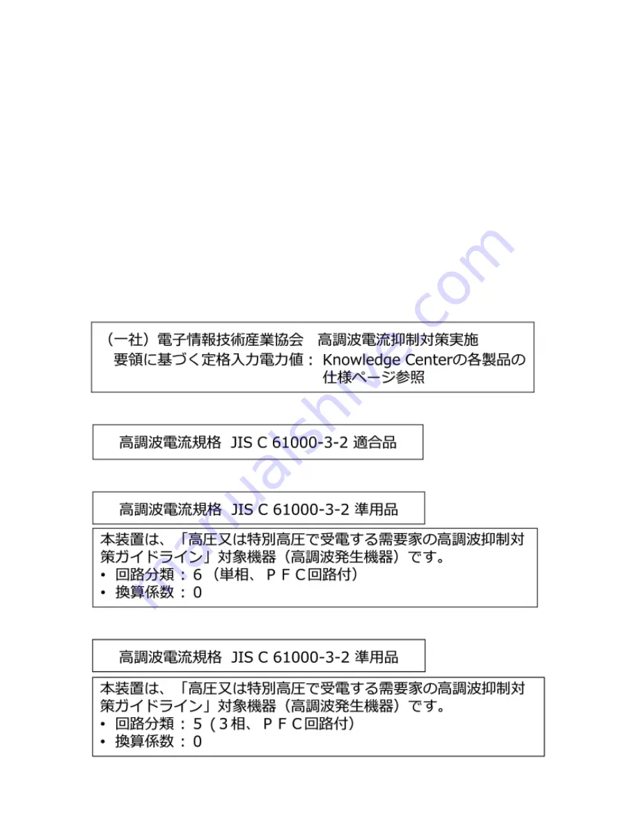
Japan Electronics and Information Technology Industries Association (JEITA) Notice

This statement applies to products less than or equal to 20 A per phase.

This statement applies to products greater than 20 A, single phase.

This statement applies to products greater than 20 A per phase, three-phase.

114  Notices

Summary of Contents for Storwize V5100 MTM 2078-424

Page 1: ...IBM Storwize V5100 Quick Installation Guide for MTM 2078 424 2078 12F 2078 24F 2078 92F and 2078 U5B IBM ...

Page 2: ... xiii The information in the IBM Environmental Notices and User Guide provided on a DVD This edition applies to version 8 release 3 modification 0 and to all subsequent modifications until otherwise indicated in new editions Copyright International Business Machines Corporation 2019 US Government Users Restricted Rights Use duplication or disclosure restricted by GSA ADP Schedule Contract with IBM...

Page 3: ...1 Installation overview 11 Unpacking the Storwize V5100 control enclosure 12 Installing support rails for the control enclosures 13 Installing a Storwize V5100 control enclosure 14 Unpacking a 2U expansion enclosure 16 Installing support rails for 2U expansion enclosures 17 Installing an optional 2U SAS expansion enclosure 20 Unpacking an optional 5U expansion enclosure 20 Installing an optional 5...

Page 4: ...ecking your web browser settings for the management GUI 81 Initializing the control enclosure 83 Completing the initial system setup 84 Verify and update the system firmware and software 85 Chapter 4 Adding an expansion enclosure to an existing system 87 Chapter 5 Adding a control enclosure to an existing system 89 Appendix A Accessibility features for the system 91 Appendix B Where to find the St...

Page 5: ... 9 Hole locations in the front of the rack 13 10 Removing enclosure end caps 15 11 Inserting the enclosure 15 12 Securing the front of the enclosure 15 13 Expansion enclosure support rails 17 14 Hole locations in the front of the rack 18 15 Opening the hinge brackets 19 16 Closing the hinge brackets 19 17 Tray containing expansion enclosure parts 21 18 Packaging materials 22 19 Packaging for fasci...

Page 6: ... rail assembly to the rack frame 42 35 Example of the required rack space 42 36 Fascia components on the expansion enclosure 43 37 Replace fascia components on the expansion enclosure 44 38 Drive assembly 45 39 Drive locations in a 5U expansion enclosure 45 40 Correct drive installation 46 41 Incorrect drive installation 46 42 Replace the drive 47 43 Aligning the 2077 92F 2077 A9F top cover 48 44 ...

Page 7: ...serted into the SAS port 57 58 SAS cable connector orientation 57 59 Connecting the SAS cables 58 60 SAS port orientation on expansion enclosures 59 61 Features on the front of the 2077 92F 2077 A9F expansion enclosure 60 62 Secure power cables 61 63 Power and SAS cable connections on the back of the enclosure 61 64 Features on the rear of the 2077 92F 2077 A9F expansion enclosure 62 65 LEDs on th...

Page 8: ... SAS cable connections on the back of the enclosure 78 79 Features on the rear of the 2077 92F 2077 A9F expansion enclosure 79 80 Technician ports 83 81 Rack space requirements for the 2078 92F models 98 82 Acoustical Declaration with Noise Hazard Notice 99 83 Rack space requirements for the 2077 2078 24F 2077 92F 2077 A9F and 2078 92F 2078 A9F expansion enclosures 106 viii ...

Page 9: ...SAS drives 29 10 Enclosure weight as FRUs are installed 29 11 Examples of supported SAS chain combinations 59 12 Display panel LEDs 63 13 Power supply unit LEDs 64 14 LED indicators on drives 65 15 LED indicators on secondary expansion modules 66 16 Expansion canister and SAS port LEDs 68 17 Supported expansion enclosure SAS drives 69 18 Other expansion enclosure parts 69 19 Power specifications p...

Page 10: ...pansion enclosures 105 31 Rack space requirements for the 2077 2078 24F 2077 92F 2077 A9F and 2078 92F 2078 A9F expansion enclosures 107 32 Clearances 107 33 Drive specifications 108 34 Acoustical specifications for 2077 2078 24F SAS expansion enclosures 108 35 Declared noise emissions for 2077 92F 2077 A9F and 2078 92F 2078 A9F SAS expansion enclosures in accordance with ISO 9296 109 36 Shock tes...

Page 11: ...A North America bi national harmonized and marked per accredited NRTL agency listings and other such derivative certifications according to corporate determinations and latest regional publication compliance standardized requirements Regulatory Model ID RMID for control system base platform FBIII RMID for 2U expansion option unit ESLS RMID for 5U expansion option unit 5U 92 Relevant Machine Type M...

Page 12: ...xii Storwize V5100 Quick Installation Guide for MTM 2078 424 2078 12F 2078 24F 2078 92F and 2078 U5B ...

Page 13: ...s and labels Review the safety notices and safety information labels before you use this product To view a PDF file you need Adobe Acrobat Reader You can download it at no charge from the Adobe website www adobe com support downloads main html IBM Systems Safety Notices This publication contains the safety notices for the IBM Systems products in English and other languages Anyone who plans install...

Page 14: ...he potential of causing death or serious personal injury D002 CAUTION A caution notice indicates the presence of a hazard that has the potential of causing moderate or minor personal injury C001 2 After you download the IBM System Safety Notices document open it 3 Under the language find the matching identification number Review the topics about the safety notices to ensure that you are in complia...

Page 15: ...tabilizer brake function before each use Do not over force moving or rolling the LIFT TOOL with stabilizer brake engaged Do not raise lower or slide platform load shelf unless stabilizer brake pedal jack is fully engaged Keep stabilizer brake engaged when not in use or motion Do not move LIFT TOOL while platform is raised except for minor positioning Do not exceed rated load capacity See LOAD CAPA...

Page 16: ...injury C048 part 2 of 2 CAUTION Removing components from the upper positions in the rack cabinet improves rack stability during a relocation Follow these general guidelines whenever you relocate a populated rack cabinet within a room or building Reduce the weight of the rack cabinet by removing equipment starting at the top of the rack cabinet When possible restore the rack cabinet to the configur...

Page 17: ...cal storm The product might be equipped with multiple power cords To remove all hazardous voltages disconnect all power cords Connect all power cords to a properly wired and grounded electrical outlet Ensure that the outlet supplies proper voltage and phase rotation according to the system rating plate Connect any equipment that will be attached to this product to properly wired outlets When possi...

Page 18: ...ONDUCTORS should terminate at this main protective earthing terminal or at points marked with R010 Special caution and safety notices This information describes special safety notices that apply to the system These notices are in addition to the standard safety notices that are supplied they address specific issues that are relevant to the equipment provided General safety When you service the Sto...

Page 19: ...he following precautions Limit your movement Movement can cause static electricity to build up around you Handle the device carefully holding it by its edges or frame Do not touch solder joints pins or exposed printed circuitry Do not leave the device where others can handle and possibly damage the device While the device is still in its antistatic bag touch it to an unpainted metal part of the sy...

Page 20: ...xx Storwize V5100 Quick Installation Guide for MTM 2078 424 2078 12F 2078 24F 2078 92F and 2078 U5B ...

Page 21: ...Center contains all of the information that is required to install configure and manage the system The information collection in the IBM Knowledge Center is updated between product releases to provide the most current documentation The information collection is available at the following website Knowledge Center IBM websites for help services and information Table 1 on page xxi lists websites wher...

Page 22: ...products www ibm com support IBM Electronic Support registration www 01 ibm com support electronicsupport Sending your comments Your feedback is important in helping to provide the most accurate and highest quality information To submit any comments send your comments by email to ibmkc us ibm com Include the following information in your email Exact publication title and version Page table or illu...

Page 23: ...port include Check all cables to make sure that they are connected Use the troubleshooting information in your system documentation The troubleshooting section of IBM Knowledge Center contains procedures to help you diagnose problems Using the documentation Sign up for the Support Line Offering If you have questions about how to use and configure the machine sign up for the IBM Support Line offeri...

Page 24: ...xxiv Storwize V5100 Quick Installation Guide for MTM 2078 424 2078 12F 2078 24F 2078 92F and 2078 U5B ...

Page 25: ...cessibility for all customers 7 Appendix B Where to find the Statement of Limited Warranty on page 93 is an appendix that describes where to find Warranty information 8 Appendix C Control enclosure requirements on page 95 is an appendix that describes the environmental requirements that you must meet to install and operate a 2077 2078 AF4 424 U5B control enclosure 9 Appendix D SAS expansion enclos...

Page 26: ...t DANGER When working on or around the system observe the following precautions Electrical voltage and current from power telephone and communication cables are hazardous To avoid a shock hazard If IBM supplied a power cord s connect power to this unit only with the IBM provided power cord Do not use the IBM provided power cord for any other product Do not open or service any power supply assembly...

Page 27: ...ed in the list Your shipment might contain extra items depending on the order Note If you purchased your equipment through a reseller some of the options might be preinstalled Contact your supplier for details Use the following checklist to check off the items in your order as you verify that they are included in your shipment __ Control enclosure or expansion enclosures Table 4 Storwize V5100 con...

Page 28: ...and adds 6 x 32 GB DIMMs __ From 0 1 of the following host interface adapter options for the two available card slots Four port 32 Gbps Fibre Channel with four small form factor pluggable SFP transceivers installed Four port 16 Gbps Fibre Channel that supports NVMe over Fabrics NVMe oF with four small form factor pluggable SFP transceivers installed Two port 25 Gbps Ethernet iWARP with iSER suppor...

Page 29: ...ferently on each node canister It is important to remember this orientation when you are installing adapters and cables Figure 1 Label showing the orientation of the node canisters and PSUs For example Figure 2 on page 5 shows the top node canister On this canister the numbering of the PCIe slots and ports goes from right to left PCIe adapter slot 1 contains a 4 port 12 Gbps SAS adapter and slot 2...

Page 30: ... for direct attach service management Control enclosure support rails The left and right control enclosure support rails are designed specifically for installation of a control enclosure The ledge on the inside of the rails supports the entire length of a control enclosure At the rear end of the control enclosure support rail the top edge curves over to capture the top edge of an inserted control ...

Page 31: ...4 2077 2078 AF4 Expansion enclosure support rails The left and right expansion enclosure support rails Figure 6 on page 8 are designed specifically for installation of an expansion enclosure The ledge on the inside of each rail supports the entire length of an expansion enclosure The expansion enclosure support rails capture the left and right rear edges of an inserted expansion enclosure This pre...

Page 32: ...ing one above the other in an inverted orientation Figure 7 on page 8 shows the canister release levers extended to either remove or replace the bottom of the two node canisters in a Storwize V5100 control enclosure The inverted upside down upper node canister is also shown in the illustration Figure 7 Rear of the Storwize V5100 enclosure Other differences between Storwize V5100 control enclosures...

Page 33: ...g tasks and worksheets before you install and initialize your system If your system contains more than one control enclosure configure a Fibre Channel switch for correct zoning between control enclosures for best results See the configuring topics in IBM Knowledge Center that contain information about zoning rules and zoning details To verify that your environment can support 2077 424 see Appendix...

Page 34: ...led distribute them evenly into rack space above and below the control enclosure to which they are to connect Do not leave gaps between the enclosures Such placement aids cabling and serviceability Leave space in the rack for future expansion enclosures but otherwise install all enclosures that constitute one system in adjacent or nearby rack space If a rack is to be only partially filled install ...

Page 35: ...ng Note If you intend to add the Storwize V5100 control enclosure to an existing system you simply install the control enclosure because the existing system is already initialized Initial setup tasks that you must complete After the hardware is installed connect a workstation to the technician port of one of the node canisters in the Storwize V5100 control enclosure and complete the following task...

Page 36: ...ssembled enclosure requires three persons unless suitable lifting equipment is available or the enclosure is unpacked and dismantled as described in the procedure Procedure 1 Cut the box tape and open the lid of the shipping carton 2 Remove the rail kit box and set it aside in a safe location 3 Lift the front and rear foam packing pieces from the carton 4 Remove the four corner reinforcement piece...

Page 37: ...The rail assembly consists of two rails that must be installed in the rack cabinet Figure 8 Control enclosure support rails 2 Working at the front of the rack cabinet identify the two standard rack units 2U of space in the rack into which you want to install the support rails Figure 9 on page 13 shows two rack units with the front mounting holes identified Figure 9 Hole locations in the front of t...

Page 38: ...to the rack cabinet flange 8 On the front of the rail press the two bracket pins into the holes in the rack flanges 9 Close the front hinge bracket to secure the rail to the rack cabinet flange 10 Secure the rear of the rail to the rear rack flange with two black M5 screws 11 Repeat the steps to secure the opposite rail to the rack cabinet 12 Repeat the procedure to install rails for each addition...

Page 39: ...osure that is partially inserted The enclosure must always be in a fully inserted position Control enclosures must be installed only on the supplied control enclosure rails Figure 11 Inserting the enclosure 4 Secure the enclosure with screws in the rack mounting screw holes on each side of the enclosure See Figure 12 on page 15 Figure 12 Securing the front of the enclosure 5 Reinstall the left and...

Page 40: ...res three persons unless suitable lifting equipment is available or the enclosure is unpacked and dismantled as described in the procedure Procedure 1 Cut the box tape and open the lid of the shipping carton 2 Remove the rail kit box and set it aside in a safe location 3 Lift the front and back foam packing pieces from the carton 4 Remove the four corner reinforcement pieces from the carton 5 Usin...

Page 41: ...springs two sets of eight bracket pins and two M5 screws Set the hardware aside for use later in the installation process 3 Install a spring on each rail a Extend the rail to its full length b Push one looped end of a spring over one stud on the inside of the rail c Stretch the spring slightly and push the other looped end of the spring onto the other stud on the inside of the rail 4 Working at th...

Page 42: ...at are appropriate for the mounting holes in your rack See Table 7 on page 18 Table 7 Selecting bracket pins for your rack Mounting holes Bracket pins Round unthreaded Use the preinstalled medium pins Round threaded Unscrew the medium pins and replace with the smaller pins that are supplied with the rails Square Unscrew the medium pins and replace with the large pins that are supplied with the rai...

Page 43: ...lange See Figure 16 on page 19 Figure 16 Closing the hinge brackets 10 On the front of the rail press the two bracket pins into the holes in the rack flanges 11 Close the front hinge bracket to secure the rail to the rack cabinet flange See Figure 16 on page 19 12 Secure the rear of the rail to the rear rack flange with an M5 screw that is provided with the rack kit 13 Repeat the steps to secure t...

Page 44: ...ight emitting diodes on the edge of the enclosure a Ensure that the serial number of the end cap matches the serial number on the rear of the enclosure b Fit the slot on the top of the end cap over the tab on the chassis flange c Rotate the end cap down until it snaps into place d Ensure that the inside surface of the end cap is flush with the chassis 6 If you are installing additional 2U SAS expa...

Page 45: ...pieces the cable management arm CMA and the slide rail kit Figure 17 on page 21 shows how the enclosure is packaged for shipment Figure 17 Tray containing expansion enclosure parts 1 Slide rail kit 2 Cable management arm 3 Fascia Note Drives are not included in installation package for the enclosure they are provided in a separate package Procedure 1 Remove the cardboard tray that contains the sli...

Page 46: ...ing foam block protectors attached to the enclosure 5 Remove the support rail kit from the box in which it was shipped 1 as shown in Figure 17 on page 21 6 Remove the 4U and 1U fascia from the boxes in which they were shipped as shown in Figure 19 on page 22 Figure 19 Packaging for fascia 1 4U fascia front 22 Storwize V5100 Quick Installation Guide for MTM 2078 424 2078 12F 2078 24F 2078 92F and 2...

Page 47: ...se the reference numbers in parentheses at the end of each notice for example D005 to find the matching translated notice in DANGER DANGER Serious injury or death can occur if loaded lift tool falls over or if a heavy load falls off the lift tool Always completely lower the lift tool load plate and properly secure the load on the lift tool before moving or using the lift tool to lift or move an ob...

Page 48: ...de front or back of a unit used for air flow through the unit Consideration should be given to the connection of the equipment to the supply circuit so that overloading of the circuits does not compromise the supply wiring or overcurrent protection To provide the correct power connection to a rack refer to the rating labels located on the equipment in the rack to determine the total power requirem...

Page 49: ...ack the rack cabinet in the original packaging material or equivalent Also lower the leveling pads to raise the casters off the pallet and bolt the rack cabinet to the pallet R002 DANGER Racks with a total weight of 227 kg 500 lb Use Only Professional Movers R003 DANGER Do not transport the rack via fork truck unless it is properly packaged secured on top of the supplied pallet R004 DANGER Main Pr...

Page 50: ...ilable on vendor s website Test verify stabilizer brake function before each use Do not over force moving or rolling the LIFT TOOL with stabilizer brake engaged Do not raise lower or slide platform load shelf unless stabilizer brake pedal jack is fully engaged Keep stabilizer brake engaged when not in use or motion Do not move LIFT TOOL while platform is raised except for minor positioning Do not ...

Page 51: ...048 part 2 of 2 CAUTION If the System slide rails are installed above EIA location 29U the ServerLIFT tool or other qualified lift tool must be used as a safety precaution for servicing Position the lift tool platform slightly below the bottom of the System drawer to account for the slight downward flex when the drawer is extended out fully on its slides Then gently raise the lift tool platform to...

Page 52: ...hipped Total weight kg lbs kg lb Enclosure FRU 01LJ607 replaces enclosure FRU P N 01LJ112 42 5 93 696 1 42 500 93 696 Rail kit 01LJ114 9 231 20 351 1 9 231 20 351 Front fascia 4U front cover 01LJ116 0 303 0 668 1 0 303 0 668 Display panel assembly 01LJ118 0 020 0 044 1 0 020 0 044 PSU fascia 1U cover 01LJ120 0 010 0 022 1 0 010 0 022 Power supply unit PSU 01LJ122 3 335 7 352 2 6 670 14 705 Seconda...

Page 53: ...re with 92 SAS drives FRU description Approximate weigh per unit Maximum supported Approximate extra weight kg lb kg lb 2 5 inch tier 0 flash drive 2 5 inch tier 1 flash drive 0 224 0 494 92 20 608 45 433 2 5 inch hard disk drive 0 304 0 670 92 27 968 61 659 3 5 inch Near Line SAS hard disk drive 0 876 1 931 92 80 592 177 675 As you install or replace FRUs the overall weight of the expansion enclo...

Page 54: ...sure 01LJ607 or 01LJ112 Secondary expansion modules Fascia 1U and 4U PSUs Expansion canisters Fan modules Fan interface board Display assembly Drives Cover 58 127 9 Note The following FRUs are installed when the enclosure is initially shipped Enclosure 01LJ607 or 01LJ112 Secondary expansion modules PSUs Expansion canisters Fan modules Fan interface board Display assembly Cover Fascia 1U and 4U Dri...

Page 55: ...ers Fan modules Fan interface board 92 2 5 inch hard disk drives Cover 86 189 6 Enclosure 01LJ607 or 01LJ112 Secondary expansion modules Fascia PSUs Expansion canisters Fan modules Fan interface board 92 3 5 inch Near Line SAS hard disk drives Cover 138 6 305 6 Conversely the overall weight of the expansion enclosure is reduced as you remove parts However even with parts removed the 5U expansion e...

Page 56: ...Figure 20 Features on the front of the 2077 92F 2077 A9F expansion enclosure 1 Display panel indicators 2 Rack retention thumb screws 3 Power supply unit indicators 4 Power supply units PSUs 5 PSU fascia 1U 6 Front fascia 4U However as Figure 21 on page 33 shows the 4U and 1U fascias are packaged separately You must attach them to the front of the 2077 92F 2077 A9F expansion enclosure as part of t...

Page 57: ... 2077 92F 2077 A9F expansion enclosure Four fan modules and two expansion enclosures are accessible from the back of the enclosure Figure 22 Features on the rear of the 2077 92F 2077 A9F expansion enclosure 1 Power cable connector for PSU 2 2 Power cable retention clamps 3 Fan module 4 Fan release latch 5 Fan fault indicator Chapter 2 Installing the system hardware 33 ...

Page 58: ...ed separately from the expansion enclosure Figure 23 2077 92F 2077 A9F support rails Cable management arm The cable management arm CMA which consists of an upper and lower assembly are packaged separately from the expansion enclosure As Figure 24 on page 35 shows each CMA assembly is attached to the rear end of the support rails 34 Storwize V5100 Quick Installation Guide for MTM 2078 424 2078 12F ...

Page 59: ...g this unit remove all appropriate subassemblies per instructions to reduce the system weight C012 Important Before you unpack move install or service the 2077 92F 2077 A9F expansion enclosure and its parts always complete the following tasks Read and follow the safety notices and instructions as described in Safety notices and considerations 2077 92F 2077 A9F on page 23 Read and follow the guidel...

Page 60: ...owever due to weight considerations you must remove some parts and then reinstall them as part of the initial installation process Note Drives are not included in installation package for the enclosure they are provided in a separate package Procedure 1 Remove the cardboard tray that contains the slide rails cable management arm and fascia from cardboard box in which the expansion enclosure was sh...

Page 61: ...on page 40 through 5 on page 41 in Installing the support rails 2077 92F 2077 A9F on page 39 8 Attach the remaining sections of the support rails to the rack as described in step 6 on page 41 in Installing the support rails 2077 92F 2077 A9F on page 39 9 Move the mechanical lift to the front of the rack Align the inner section of the rails with the mid section of the rails that are extending from ...

Page 62: ... 17 Remove the cable management arm assembly from its packaging 2 in Figure 25 on page 36 18 Attach the cable management arm as described in Installing or replacing the cable management arm 2077 92F 2077 A9F on page 51 19 Connect the SAS cables as described in Removing and installing a SAS cable 2077 92F 2077 A9F on page 55 20 Connect the power cables Removing the top cover 2077 92F 2077 A9F To co...

Page 63: ...location Replace the cover 5 To reinstall the cover or replace it with one from FRU stock follow the procedure in Installing or replacing the top cover 2077 92F 2077 A9F on page 48 Installing the support rails 2077 92F 2077 A9F You must install the support rails before you can install a 2077 92F 2077 A9F expansion enclosure in a rack Procedure 1 Locate the hardware that is used to install the rail...

Page 64: ...ives are installed the expansion enclosure is heavy Install the support rails and enclosure at the lowest available position Do not install the rails and enclosure above position U25 in the rack 3 Remove the inner member of the rail Push the tab a and slide the middle rail member back as shown in Figure 31 on page 40 Figure 31 Detaching the inner rail section 4 Use four M4 screws to attach the inn...

Page 65: ... rail onto each side of the expansion enclosure as shown in Figure 33 on page 41 Figure 33 Attaching the inner rail section to the enclosure 6 Use the M5 screws to install the outer rail member and bracket assembly to the rack as shown in Figure 34 on page 42 Chapter 2 Installing the system hardware 41 ...

Page 66: ... rack frame For example Figure 35 on page 42 shows the front of the rail that is attached to the frame Figure 35 Example of the required rack space 42 Storwize V5100 Quick Installation Guide for MTM 2078 424 2078 12F 2078 24F 2078 92F and 2078 U5B ...

Page 67: ...e other Figure 36 Fascia components on the expansion enclosure Note When the expansion enclosure is shipped the 4U and 1U fascia are not installed You must install them as part of the initial installation process Procedure Attach the front 4U fascia 1 Align the front 4U fascia with the enclosure so that the thumbscrews go through the holes on each side As Figure 37 on page 44 shows this action ali...

Page 68: ...f the expansion enclosure However to maintain operating temperature do not keep the cover off an operational enclosure for more than 15 minutes The reduction in airflow through the enclosure might cause the enclosure or its components to shut down to protect from overheating Ensure that the drive that you are replacing is not a spare or a member of an array The drive status is shown in Pools Inter...

Page 69: ...Locate the empty drive slot to receive the new drive or that contains the faulty drive that you want to replace Note When a drive is faulty the amber fault indicator is lit 3 in Figure 38 on page 45 Do not replace a drive unless the drive fault indicator is on or you are instructed to do so by a fix procedure A label on the enclosure cover Figure 39 on page 45 shows the drive locations in the encl...

Page 70: ...ves are installed in row B even though row A contains empty drive slots Figure 41 Incorrect drive installation 4 Touch the static protective package that contains the drive to any unpainted metal surface on the enclosure Wear an anti static wrist strap to remove the drive from the package 5 Ensure that the drive handle 1 in Figure 42 on page 47 of the drive assembly is in the open unlocked positio...

Page 71: ...age 47 9 Ensure the toe on the bottom of the latch is fully engaged with the partition in the chassis 10 Ensure that the top toe of the latch is also fully engaged 4 in Figure 42 on page 47 11 Repeat steps 4 on page 46 through 10 on page 47 for each drive you are replacing Chapter 2 Installing the system hardware 47 ...

Page 72: ...s of completing other service tasks When the cover is removed the reduction in airflow through the enclosure might cause the enclosure or its components to shut down to protect from overheating About this task To install or replace the top cover on the 2077 92F 2077 A9F expansion enclosure complete the following steps Procedure 1 Carefully lower the cover and ensure that it is aligned correctly wi...

Page 73: ... might also need to slide the enclosure back in to the rack About this task Important The 2077 92F 2077 A9F expansion enclosure is heavy Before you install the expansion enclosure in the rack for the first time or replace it in the rack to complete a service task review and implement the following tasks Always use a suitably rated mechanical lift or four persons to raise the enclosure to install i...

Page 74: ...g the enclosure you must also perform the following tasks Reinstall all of the following parts Cover Drives Fan modules Power supply units and 1U fascia Secondary expander modules Expansion canisters and SAS cables Reconnect both power cables to the expansion enclosure Procedure 1 Fully extend the left and right drawer sections from the rack to lock the rails in the extended position 1 in Figure 4...

Page 75: ...he enclosure Press both release tabs forward to unlock the drawer mechanism 3 in Figure 47 on page 51 6 Push the enclosure firmly into the rack 4 in Figure 47 on page 51 7 Tighten the locking thumb screws 5 in Figure 47 on page 51 to secure the enclosure in the rack 8 Reconnect power to the expansion enclosure Installing or replacing the cable management arm 2077 92F 2077 A9F Use these procedures ...

Page 76: ... support rails Figure 49 Upper and lower cable management arms Procedure 1 Remove the loop straps from the upper and lower CMA assemblies The straps are used only for shipping Installing the upper CMA assembly Figure 50 on page 53 shows the connectors on the upper CMA assembly 52 Storwize V5100 Quick Installation Guide for MTM 2078 424 2078 12F 2078 24F 2078 92F and 2078 U5B ...

Page 77: ...nnector of the upper CMA assembly 1 to the inner member of the left support rail 2 as shown in Figure 51 on page 53 Figure 51 Install the inner connector of the upper CMA to the inner member of the support rail 3 Install the outer connector of the upper CMA assembly 3 to the outer member of the left support rail 4 as shown in Figure 52 on page 53 Figure 52 Install the outer connector of the upper ...

Page 78: ...shows the upper and lower CMA assemblies as they are aligned to the support rails The support rail connector of the upper CMA attaches to the right rail The support rail connector of the lower CMA 11 attaches to the left rail Figure 54 Comparing the location of the components of the CMA assemblies 7 Inner connector on lower CMA 8 Connector base on inner rail member 9 Outer connector on lower CMA 1...

Page 79: ...s task Be careful when you are replacing the hardware components that are located in the back of the system Do not inadvertently disturb or remove any cables that you are not instructed to remove If you replace more than one cable record which two ports canisters and enclosures each cable connects so you can match the connections with the replacement cables The system cannot operate if the SAS cab...

Page 80: ...7 Connect the SAS cable to the SAS port with blue tab above the connector that is facing towards the top of the node You hear or feel a click when the cable is successfully inserted You cannot disconnect the cable without pulling on the blue tag 8 Route the SAS cables through the cable management arms as shown in Figure 56 on page 56 Figure 56 Example of SAS cables routed through the cable managem...

Page 81: ...sures into the rack you must connect them to each system that will use them The system requires software version 7 8 0 or later Do not connect the expansion enclosure if software version 7 8 0 is not installed on the system About this task This task applies if you are installing a 2078 92F 2078 A9F expansion enclosure Note When you insert SAS cables ensure that the connector is oriented correctly ...

Page 82: ...storage attachment ensure that these ports are accessible The nodes and the enclosures themselves Access is required to the hardware for servicing and for safely removing and replacing components by using two or more people Procedure 1 Install the cables as shown in Figure 59 on page 58 Note Figure 59 on page 58 shows the cable connections between the SAS enclosures and the control enclosure It do...

Page 83: ...nclosures 1 Input SAS port 2 Output SAS port Powering on the optional 2077 92F 2077 A9F expansion enclosures Use the following procedure to provide power to the 2077 92F 2077 A9F expansion enclosure as part of the initial installation process or after a service procedure Before you begin Important Before you connect the power cables to the rear of the enclosure always check that the expansion encl...

Page 84: ... enclosure Power is provided by plugging a C19 C20 power cable into each power supply unit and if necessary turning on the power source The expansion enclosure does not have a power button Procedure 1 Connect the C19 C20 power cables to the power connectors on the rear of the expansion enclosure The enclosure automatically powers on and begins its Power On Self Tests POST 2 Secure the power cables...

Page 85: ... slide the expansion enclosure out of the rack to perform service tasks Figure 63 Power and SAS cable connections on the back of the enclosure 3 Verify that the expansion enclosure and its components are operating as expected On the back of the expansion enclosure all four fans and the expansion canister indicators 3 and 8 in Figure 64 on page 62 become active when the power is connected Chapter 2...

Page 86: ...nt Log to view enclosure and component events and complete any remaining fix procedures Powering off the expansion enclosure 2077 92F 2077 A9F Before you power down a 2077 92F 2077 A9F expansion enclosure review the following procedure Before you begin When you power off an expansion enclosure the drives in that enclosure are no longer available to the control enclosure The SAS chain also breaks A...

Page 87: ...LEDs on the front of the expansion enclosure As Figure 65 on page 63 shows the front of the 2077 92F 2077 A9F expansion enclosure contains LEDs for the display panel 1 and for each of the power supply units 3 Figure 65 LEDs on the front of the expansion enclosure 1 Display panel LEDs 2 Rack retention thumb screws 3 Power supply unit LEDs 4 Power supply units PSUs 5 PSU fascia 1U 6 Front fascia 4U ...

Page 88: ...its own a set of LEDs as shown in Figure 66 on page 64 Figure 66 LEDs on the front of a power supply unit 1 Input power 2 DC power 3 Fault indicator Table 13 on page 64 explains the function and status that is indicated by each of the LEDs The power cords for each PSU are accessible from the rear of the expansion enclosure 1 as shown in Figure 69 on page 67 Table 13 Power supply unit LEDs Function...

Page 89: ...ive assembly Table 14 on page 65 describes the meaning of the LEDs on each drive Table 14 LED indicators on drives Function Color Status Description 2 Activity Green On The drive is ready to be used Flashing The drive is operating and I O is occurring Off The drive is not installed or an installed drive is not ready to be used 3 Fault Amber On A fault occurred on the drive The LED is turned off wh...

Page 90: ...used Off The secondary expansion module is not receiving power 2 Fault Amber On Not used Flash The secondary expansion module is being identified Off The secondary expansion module is operating normally LEDs on the rear of the expansion enclosure Figure 69 on page 67 shows the rear view of a 2077 92F 2077 A9F expansion enclosure LEDs on the rear of the enclosure provide information about each fan ...

Page 91: ...the expansion enclosure contains two expansion canisters Each expansion canister contains its own set of LEDs as shown in Figure 70 on page 67 The LEDs provide status information about the expansion canister itself and the SAS connections Figure 70 LEDs on the back of the expansion canister 1 Canister fault 2 Canister status 3 Canister power 4 and 6 SAS link fault 5 and 7 SAS link operational 8 Ca...

Page 92: ... connected but not all 4 The phys are not operating at the same speed All phys are not connected to the same remote port One or more of the connected lanes are attached to a different address 5 and 7 SAS link operational Green Off No link connection on any lane The connection is down On The SAS link is active At least one of the four lanes is connected Storwize V5100 5U expansion enclosure parts O...

Page 93: ...For systems with a 1 year warranty 2077 xxx For systems with a 3 year warranty 2078 xxx 3 84 TB tier 1 flash drive 01LJ046 For systems with a 1 year warranty 2077 xxx For systems with a 3 year warranty 2078 xxx 7 68 TB tier 1 flash drive 01LJ047 For systems with a 1 year warranty 2077 xxx For systems with a 3 year warranty 2078 xxx 15 36 TB tier 1 flash drive 01LJ048 For systems with a 1 year warr...

Page 94: ... enclosure with FRU part number 01LJ112 Avoid contact with the connectors on the main board 01LJ126 Fan module The expansion enclosure contains four fan modules 01LJ128 Expansion canister 01LJ130 Cable management arms CMA The part contains the upper and lower CMA 01LJ132 Top cover 01LJ134 Fan interface board 01LJ607 Note Replaces enclosure FRU P N 01LJ112 Enclosure Includes the drive board signal ...

Page 95: ...e in the system ensure that port 2 of every node canister is connected to the same network to provide access if the configuration node fails Connecting Fibre Channel cables to the control enclosure If your system has one or more Fibre Channel adapters installed use Fibre Channel cables to connect the two node canisters in the enclosure to the switches in the Fibre Channel SAN Before you begin Refe...

Page 96: ...ting SAS cables between enclosures you must follow a list of guidelines to ensure that your configuration is valid Do not begin connecting the cables until you have read Figure 72 on page 73 Procedure To install the cables complete the following steps 1 Using the supplied SAS cables connect the control enclosure to the expansion enclosure at rack position 1 as shown in Figure 72 on page 73 a Conne...

Page 97: ...ion enclosures in two chains 10Uin the upper chain above the control enclosure and 10U in the lower chain 4 If additional control enclosures are installed repeat this cabling procedure on each control enclosure and its expansion enclosures When using more than one control enclosure divide the total number of expansion enclosures among the control enclosures to enhance performance SAS cabling guide...

Page 98: ...AS cable connectors Guidelines Be aware of the following guidelines when you connect a 2077 424 control enclosure to the SAS ports in 2U and 5U expansion enclosures 2077 424 systems support 4 port SAS interface adapters No more than ten 2U expansion enclosures can be chained to SAS port 1 of a node canister The expansion enclosures in this chain should be installed below the control enclosure as s...

Page 99: ...d in all empty host interface adapter slots Open bays or slots disrupt the internal air flow causing the drives to receive insufficient cooling Procedure To power on the 2U SAS expansion enclosures complete the following steps 1 Use the supplied power cords to connect both power supply units of the first expansion enclosure to their power sources If the power sources have circuit breakers or switc...

Page 100: ...lowing procedure to provide power to the 2077 92F 2077 A9F expansion enclosure as part of the initial installation process or after a service procedure Before you begin Important Before you connect the power cables to the rear of the enclosure always check that the expansion enclosure is secured in the rack If needed tighten the thumbscrews on the front of the enclosure 2 in Figure 76 on page 77 t...

Page 101: ...it and if necessary turning on the power source The expansion enclosure does not have a power button Procedure 1 Connect the C19 C20 power cables to the power connectors on the rear of the expansion enclosure The enclosure automatically powers on and begins its Power On Self Tests POST 2 Secure the power cables in the cable retainer at each power connector on the rear of the enclosure as shown in ...

Page 102: ...re out of the rack to perform service tasks Figure 78 Power and SAS cable connections on the back of the enclosure 3 Verify that the expansion enclosure and its components are operating as expected On the back of the expansion enclosure all four fans and the expansion canister indicators 3 and 8 in Figure 79 on page 79 become active when the power is connected 78 Storwize V5100 Quick Installation ...

Page 103: ...t of a service procedure view the information in the management GUI to confirm that the enclosure is operating as expected You can also access the Event Log to view enclosure and component events and complete any remaining fix procedures Powering on the system After you install all hardware components you must power on the system and check its status About this task Attention Do not power on the s...

Page 104: ...switches Notes Each enclosure has two power supply units To provide power failure redundancy connect the two power cords to separate power circuits Ensure that each power cable is secured to each PSU on the back of the enclosure What to do next Next you will connect an Ethernet cable to the technician port on the control enclosure and initialize the system 80 Storwize V5100 Quick Installation Guid...

Page 105: ...the browsers if the vendors do not remove or disable function that the product relies upon For browser levels higher than the versions that are certified with the product customer support accepts usage related and defect related service requests If the support center cannot re create the issue support might request the client to re create the problem on a certified browser version Defects are not ...

Page 106: ...owser 2 Enable cookies in your web browser For Microsoft Internet Explorer IE 11 and Microsoft Edge running on Microsoft Windows 10 cookies are enabled by default and require no additional configuration For Mozilla Firefox complete the following steps a On the menu bar in the Firefox browser window click Tools Options b On the Options window select Privacy c Set Firefox will to Use custom settings...

Page 107: ...e the following steps a On the menu bar in the Firefox browser window click Tools Options b On the Options window select Content c Click Advanced by the Enable JavaScript setting d Select Disable or replace context menus e Click OK to close the Advanced window f Click OK to close the Options window g Refresh your browser Initializing the control enclosure Before you initiate the system you must co...

Page 108: ...ssw0rd After you log in the initial setup wizard helps you get started Use the information on your worksheets to inform your inputs a Choose and create a new password b Configure licensed functions If encryption was purchased you can activate it now or later by opening the management GUI and selecting Settings Security Encryption The base license entitles 2077 424 to all licensed functions such as...

Page 109: ...on license click Enable Encryption to complete the encryption setup wizard 8 If exactly two control enclosures are in the system you must set up a quorum disk or application outside of the system If the two control enclosures lose communication with each other the quorum disk prevents both I O groups from going offline For more information see the Configuring quorum topic in the IBM Knowledge Cent...

Page 110: ...86 Storwize V5100 Quick Installation Guide for MTM 2078 424 2078 12F 2078 24F 2078 92F and 2078 U5B ...

Page 111: ... Connect the expansion enclosure attachment cables 4 Connect the power cables and wait for the SAS light emitting diodes LEDs to illuminate 5 Start the management GUI 6 Go to Monitoring System 7 In the management GUI select Monitoring System On the System Overview page select Add Enclosure When a new enclosure is cabled correctly to the system the Add Enclosure action automatically displays on the...

Page 112: ...88 Storwize V5100 Quick Installation Guide for MTM 2078 424 2078 12F 2078 24F 2078 92F and 2078 U5B ...

Page 113: ...orts to connect to each other 5 Start the management GUI on the existing system 6 In the management GUI select Monitoring System On the System Overview page select Add Enclosure When a new enclosure is cabled correctly to the system the Add Enclosure action automatically displays on the System Overview page If this action does not appear review the installation instructions to ensure the new enclo...

Page 114: ...90 Storwize V5100 Quick Installation Guide for MTM 2078 424 2078 12F 2078 24F 2078 92F and 2078 U5B ...

Page 115: ...y standard devices ports and connectors The system online documentation and its related publications are accessibility enabled The accessibility features of the online documentation are described in Keyboard navigation You can use keys or key combinations for operations and to initiate menu actions that can also be done through mouse actions You can go to the system online documentation from the k...

Page 116: ...92 Storwize V5100 Quick Installation Guide for MTM 2078 424 2078 12F 2078 24F 2078 92F and 2078 U5B ...

Page 117: ...y The Statement of Limited Warranty is available in both hardcopy format and in the Storwize V5100 IBM Knowledge Center The Statement of Limited Warranty is included in hardcopy form with your product It can also be ordered from IBM Copyright IBM Corp 2019 93 ...

Page 118: ...94 Storwize V5100 Quick Installation Guide for MTM 2078 424 2078 12F 2078 24F 2078 92F and 2078 U5B ...

Page 119: ...not correctly wired could place hazardous voltage on the metal parts of the system or the devices that attach to the system It is the responsibility of the customer to ensure that the outlet is correctly wired and grounded to prevent an electrical shock R001 part 1 of 2 CAUTION Do not install a unit in a rack where the internal rack ambient temperatures will exceed the manufacturer s recommended a...

Page 120: ...provide a reliable ground for each enclosure in the rack Power requirements for each power supply two per enclosure Ensure that your environment meets the following power requirements To aid in power and cooling requirements planning Table 19 on page 96 lists the rating of each power supply unit PSU by enclosure The power that is used by the system depends on various factors including the number o...

Page 121: ... 29 C 84 F Shipping 40 C to 60 C 40 F to 140 F 5 to 100 condensing but not precipitating Dimensions and weight requirements for rack installation Ensure that space is available in a standard 19 rack that is capable of supporting the enclosure The rack rail kit supports racks with either threaded round or square rail mounting holes The following table lists the dimensions and weights of the enclosu...

Page 122: ...ces Location Additional space requirements Reason Left and right sides 50 mm 2 in Cooling air flow Back Minimum 100 mm 4 in Cable exit Supported drives Table 24 on page 98 provides drive specifications for your Storwize V5100 system Table 24 Drive specifications Model and type 3 5 inch drives 2 5 inch drives 2077 424 or 2078 U5B Control Enclosure with 24 2 5 inch drive slots 24 dual port NVMe driv...

Page 123: ...Table 26 on page 99 provide the shock and vibration testing results for your Storwize V5100 system Table 25 Shock testing results Shock categories Test level Performance Operational 5 g 10 ms 1 2 Sine 25 g 10 ms Non operational 30 g 10 ms 1 2 Sine 75 g 11 ms Table 26 Vibration testing results Vibration categories Test level Performance Operational 0 21 grms 5 500 Hz Random Throughput loss 10 FCAL ...

Page 124: ...100 Storwize V5100 Quick Installation Guide for MTM 2078 424 2078 12F 2078 24F 2078 92F and 2078 U5B ...

Page 125: ...the following power requirements To aid in power and cooling requirements planning Table 27 on page 101 lists the rating of each power supply unit PSU by enclosure The power that is used by the system depends on several factors including the number of enclosures and drives in the system and the ambient temperature Table 27 Power specifications per power supply Model and type PSU Input power requir...

Page 126: ...78 92F 2078 A9F power supplies The power and thermal measurements that are shown in Table 28 on page 102 were obtained in the specific operating environment and under the conditions described These measurements are presented as an illustration measurements that are obtained in other operating environments might vary Conduct your own testing to determine specific measurements for your environment T...

Page 127: ...closure with 24 10 K SAS drives 175 W 2077 2078 12F or 2077 2078 24F or 2077 2078 AFF 1 enclosure with 24 15 K SAS drives 234 W 2077 2078 12F or 2077 2078 24F or 2077 2078 AFF 1 enclosure with 12 7 2 K nearline SAS drives 158 W 2077 92F 2077 A9F 2078 92F 2078 A9F 1 enclosure with 92 10 TB nearline SAS drives 848 W Appendix D SAS expansion enclosure requirements 103 ...

Page 128: ...s in the rear of the enclosure Airflow for the lower 1U of the 5U enclosure is driven through the power supplies via 40mm X 56mm fans Air continues through the chassis cooling the ESMs or controllers and exits the rear of the enclosure The combined power and cooling module exhausts air from the rear of each canister Ensure that your environment falls within the ranges that are shown in Table 29 on...

Page 129: ...tallation Ensure that space is available in a standard 19 rack that is capable of supporting the enclosure The rack rail kits support racks with either threaded round or square rail mounting holes The following table lists the dimensions and weights of the expansion enclosures Table 30 Physical characteristics of the expansion enclosures Enclosure Height Width Depth Maximum weight Drive ready with...

Page 130: ...model enclosures need 968 mm from the rack front post to the back of the cable management arm CMA In addition allow 905 mm from the front post to the back of the enclosure To allow space for the power cables provide 60 to 70 mm from the back of the enclosure Figure 83 on page 106 shows the rack space requirements for the 2077 2078 24F 2077 92F 2077 A9F and 2078 92F 2078 A9F expansion enclosures Fi...

Page 131: ... 23 4 in 795 mm 31 3 in 2077 92F 2077 A9F 2078 92F 2078 A9F 680 mm 26 8 in 800 mm 31 5 in Additional rack space requirements Ensure that these additional space requirements as shown in Table 32 on page 107 are available around the enclosures Table 32 Clearances Location Additional space requirements Reason Left and right sides 50 mm 2 in Cooling air flow Back Minimum 100 mm 4 in This space is not ...

Page 132: ...8 92F 2078 A9F 2 5 Flash Drive 1 6 TB 1 92 TB 3 2 TB 3 84 TB 7 68 TB 15 36 TB Acoustical specifications for Storwize V5100 SAS expansion enclosures The following table provides the acoustical specifications for the 2077 2078 24F SAS expansion enclosures Table 34 Acoustical specifications for 2077 2078 24F SAS expansion enclosures Model and type Acoustical output per enclosure 2077 2078 24F Less th...

Page 133: ...installation This system is available with an optional acoustical door feature that can help reduce the noise emitted from this system The actual sound pressure levels in your installation depend upon a variety of factors including the number of racks in the installation the size materials and configuration of the room where you designate the racks to be installed the noise levels from other equip...

Page 134: ... 3 g 2 200Hz Sine 5 g Rotational vibration Normal operation performance measurements in enclosure with no external vibration Throughput loss for all drives of the same type within performance profile 110 Storwize V5100 Quick Installation Guide for MTM 2078 424 2078 12F 2078 24F 2078 92F and 2078 U5B ...

Page 135: ... Japan Ltd 19 21 Nihonbashi Hakozakicho Chuo ku Tokyo 103 8510 Japan INTERNATIONAL BUSINESS MACHINES CORPORATION PROVIDES THIS PUBLICATION AS IS WITHOUT WARRANTY OF ANY KIND EITHER EXPRESS OR IMPLIED INCLUDING BUT NOT LIMITED TO THE IMPLIED WARRANTIES OF NON INFRINGEMENT MERCHANTABILITY OR FITNESS FOR A PARTICULAR PURPOSE Some jurisdictions do not allow disclaimer of express or implied warranties ...

Page 136: ...se is entirely coincidental COPYRIGHT LICENSE This information contains sample application programs in source language which illustrate programming techniques on various operating platforms You may copy modify and distribute these sample programs in any form without payment to IBM for the purposes of developing using marketing or distributing application programs conforming to the application prog...

Page 137: ...asts Warning This equipment is compliant with Class A of CISPR 32 In a residential environment this equipment may cause radio interference Germany Notice Deutschsprachiger EU Hinweis Hinweis für Geräte der Klasse A EU Richtlinie zur Elektromagnetischen Verträglichkeit Dieses Produkt entspricht den Schutzanforderungen der EU Richtlinie 2014 30 EU zur Angleichung der Rechtsvorschriften über die elek...

Page 138: ...Deutschland GmbH Technical Relations Europe Abteilung M456 IBM Allee 1 71139 Ehningen Germany Tel 49 800 225 5426 e mail Halloibm de ibm com Generelle Informationen Das Gerät erfüllt die Schutzanforderungen nach EN 55024 und EN 55032 Klasse A Japan Electronics and Information Technology Industries Association JEITA Notice This statement applies to products less than or equal to 20 A per phase This...

Page 139: ...Japan Voluntary Control Council for Interference VCCI Notice Korea Notice People s Republic of China Notice Russia Notice Taiwan Notice Notices 115 ...

Page 140: ...erence in which case the user will be required to correct the interference at his own expense Properly shielded and grounded cables and connectors must be used in order to meet FCC emission limits IBM is not responsible for any radio or television interference caused by using other than recommended cables and connectors or by unauthorized changes or modifications to this equipment Unauthorized cha...

Page 141: ...cation guidelines 9 10 power cords 75 rails 17 expansion enclosure SAS cable 2077 92F 2077 A9F 55 replacing 55 F feedback xxii H homologation statement 113 L LEDs expansion enclosure 76 M management GUI adding an expansion enclosure 87 N notices environmental xix P power requirements system 96 power cords 75 80 powering on the system 79 R rails expansion enclosure 17 reader feedback xxii replacing...

Page 142: ... AC power 96 dimensions and weight 97 enclosures acoustic output 98 99 humidity without redundant AC power 96 power requirements for each PSU 96 weight and dimensions 97 T technician port 83 trademarks 112 V vibration specifications 99 W web browsers configuring 81 requirements 81 118 Storwize V5100 Quick Installation Guide for MTM 2078 424 2078 12F 2078 24F 2078 92F and 2078 U5B ...

Page 143: ......

Page 144: ...IBM Part Number 02YC382 1P P N 02YC382 ...

Reviews: