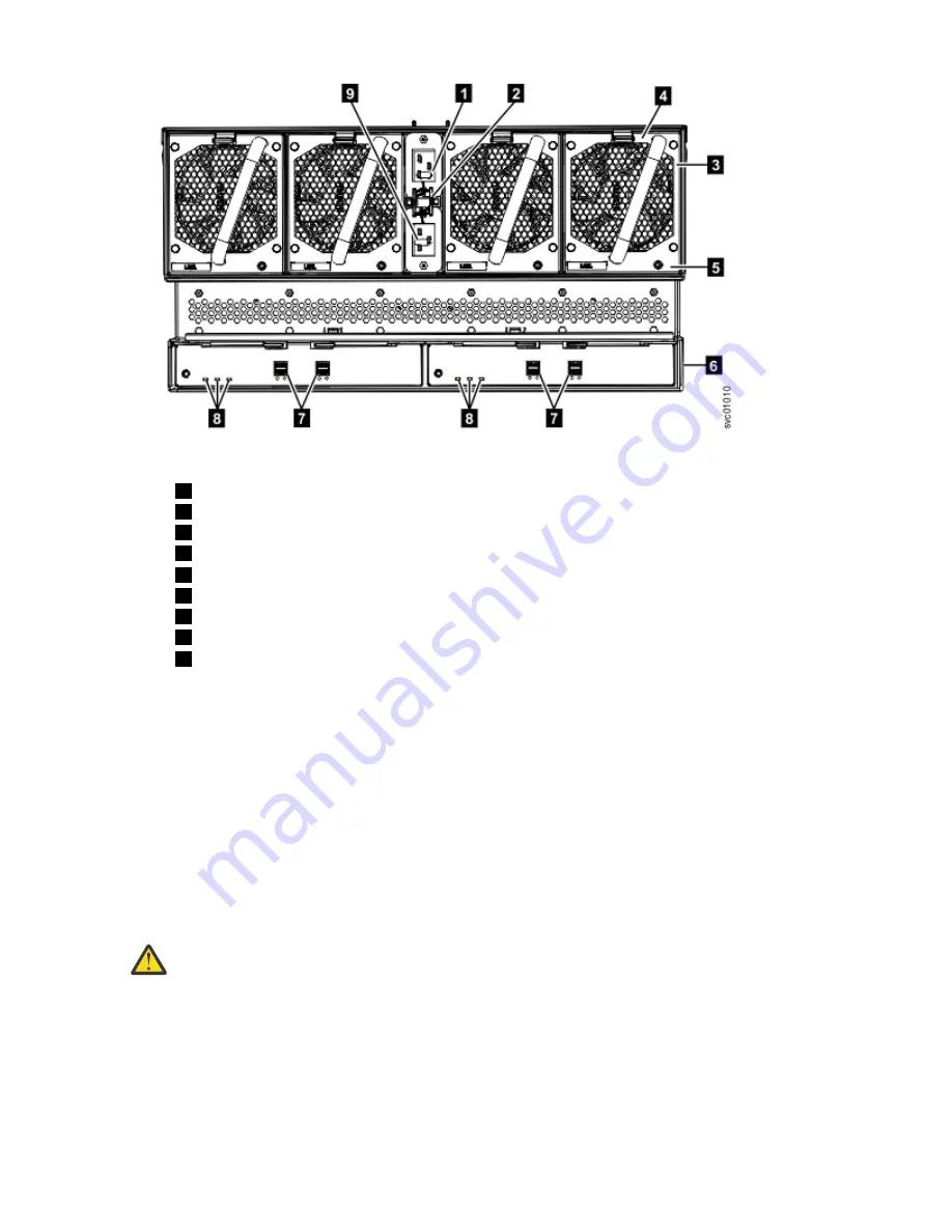
Figure 79. Features on the rear of the 2077-92F, 2077-A9F expansion enclosure
1
Power cable connector for PSU 2
2
Power cable retention clamps
3
Fan module
4
Fan release latch
5
Fan fault indicator
6
Expansion canister
7
SAS ports and indicators
8
Expansion canister indicators
9
Power cable connector for PSU 1
4. Verify that the system recognizes the expansion enclosure.
In the management GUI, view information about the system status and the expansion enclosure.
• If a new expansion enclosure was installed, make sure that the enclosure was discovered by the
system. A newly recognized expansion enclosure is visible in the management GUI.
• If the expansion enclosure was powered off as part of a service procedure, view the information in
the management GUI to confirm that the enclosure is operating as expected. You can also access
the Event Log to view enclosure and component events and complete any remaining fix procedures.
Powering on the system
After you install all hardware components, you must power on the system and check its status.
About this task
Attention: Do not power on the system with any open bays or slots. Open bays or slots disrupt the
internal air flow, causing the drives to receive insufficient cooling.
• Every unused drive bay must be occupied by a filler panel.
• Filler panels must be installed in all empty host interface adapter slots.
Procedure
To power on the system, complete the following steps.
1. All expansion enclosures should already be powered on.
2. Wait for all expansion enclosures to finish powering on.
Chapter 2. Installing the system hardware 79
Summary of Contents for Storwize V5100 MTM 2078-12F
Page 143: ......


