IBM Slicestor 2584 Installation Manual Download Page 34

Table 4. Drawer LED states (continued)

Sideplane
OK / power
(green)

Sideplane
fault (amber)

Logical fault
(amber)

Cable fault
(amber)

Activity bar
graph (green)

Status

On

On

X

X

X

Drive failure has occured causing
loss of availability or redundancy

On

X

On

X

X

Drive fault (Host indicated)

On

X

Flashing

X

X

Arrays in impacted state

Off

X

X

On

Off

Cable fault

On

Off

Off

Off

On*

Drive activity

*The Activity Bar Graph is a 6-segment drive activity meter, showing activity of the SAS interface to the sideplane.
For zero activity, no segments are lit, scaling linearly until all segments are lit when the interface is transferring data
at full capacity.

X = disregard

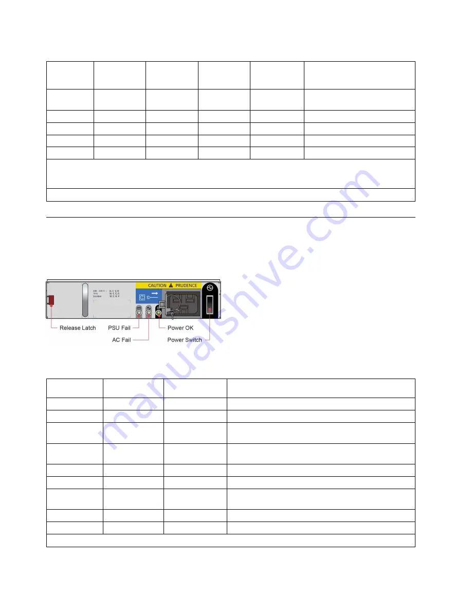
Power supply unit (PSU) LEDs

Each PSU has its own indicators.

The following figure shows the LEDs for the power supply.

Table 5. PSU LED states

PSU fail
(amber)

AC fail (amber

Power OK (green) Status

Off

Off

Off

No AC power to either PSU

On

On

Off

PSU present but not supplying power

Off

Off

On

Main AC present, switch on; PSU is providing power
output.

Off

Off

Flashing

AC power present, PSU in Standby mode (meaning the
other PSU is currently providing power output)

Flashing

Flashing

Off

PSU firmware download

On

On

Off

PSU alert state, usually due to critical temperature

Off

On

Off

Main AC to this PSU is missing; this PSU is now on
standby, and the other PSU is OK

On

On

On

GEM software lost communication with PSU

On

X

Off

PSU failed.

X = disregard

Figure 18. PSU LEDs

20

Slicestor

®

2584 Installation Guide

Summary of Contents for Slicestor 2584

Page 1: ...IBM Cloud Object Storage System Version 3 13 1 Slicestor 2584 Installation Guide IBM...

Page 2: ...ental notices v The information in the IBM Environmental Notices and User Guide provided on a DVD This edition applies to IBM Cloud Object Storage System Slicestor 2584 and is valid until replaced by...

Page 3: ...n 5 Before you begin 5 Unpacking the storage system 5 Chapter 3 Installing the appliance into a rack 7 Mounting the system into a rack 7 Enclosure layout 8 Installing and removing disk drives in carri...

Page 4: ...iv Slicestor 2584 Installation Guide...

Page 5: ...moving a DDIC 11 8 Removing a cooling module 1 11 9 Removing a cooling module 2 12 10 Removing a PSU 1 12 11 Removing a PSU 2 13 12 Removing a module 1 6Gb s SAS EBOD module shown 13 13 Removing a mod...

Page 6: ...vi Slicestor 2584 Installation Guide...

Page 7: ...emissions in accordance with ISO 9296 1 2 3 xiii 2 SBB compute module LED descriptions 17 3 Ops module LED states 18 4 Drawer LED states 19 5 PSU LED states 20 6 Cooling module LED states 21 Copyright...

Page 8: ...viii Slicestor 2584 Installation Guide...

Page 9: ...a danger notice Numbers in parentheses refer to message numbers in the IBM Safety Notices publication G229 9054 which is included with your product CAUTION A caution notice indicates the presence of...

Page 10: ...l possible unsafe conditions are corrected Assume that an electrical safety hazard is present Perform all continuity grounding and power checks specified during the subsystem installation procedures t...

Page 11: ...nditions due to uneven mechanical loading always install the heaviest devices in the bottom of the rack cabinet Always install servers and optional devices starting from the bottom of the rack cabinet...

Page 12: ...the correct power connection to a rack refer to the rating labels located on the equipment in the rack to determine the total power requirement of the supply circuit For sliding drawers Do not pull o...

Page 13: ...Model S03 35 deg C room ambient 9 3 9 3 75 75 Model S03 25 deg C room ambient w Acoustical doors Feature codes FC EC07 back FC EC08 front 7 4 7 4 55 55 Model S03 35 deg C room ambient w Acoustical doo...

Page 14: ...xiv Slicestor 2584 Installation Guide...

Page 15: ...ection provided by the equipment might be impaired v All rear modules are part of the fire enclosure and must only be removed when a replacement can be immediately added The system must not be run wit...

Page 16: ...ning both drawers at the same time Do not attempt to force open a drawer when the other drawer is already open Rack system precautions The enclosure must be mounted in a rack Consider the following sa...

Page 17: ...ing plug in modules and components Avoid contact with backplane components module connectors and other potential sources of ESD Product rating Product rating information can also be found on the back...

Page 18: ...4 Slicestor 2584 Installation Guide...

Page 19: ...enclosure ensure that you have the following accessories v Power Cord v Rack kit if installing within a rack Refer to your supplier for a list of qualified accessories for use with the enclosure The a...

Page 20: ...Figure 1 Unpacking the storage system 6 Slicestor 2584 Installation Guide...

Page 21: ...les and components Avoid contact with backplane components module connectors and other potential sources of ESD ESD damage is not covered by warranty Note Rail Kit Adjustment Range Inside of the front...

Page 22: ...e enclosure fully home on its rails 5 Fasten the front of the enclosure using the enclosure fastening screws and washers x4 as shown in Figure 2 6 Fix the rear of the enclosure to the hold down bracke...

Page 23: ...LEDs on the front of the enclosure and the modules on the back For detailed information about the LEDs see Chapter 4 LED states on page 17 Figure 3 Drive numbering for drawer 1 top Figure 4 Drive num...

Page 24: ...IC into the slot and then push it down until it stops as shown in the following figure 2 Slide the top latch in the direction of the arrow until the latch clicks into place see Figure 6 Removing a DDI...

Page 25: ...void damaging the connector pins Do not install if any pins appear to be bent CAUTION Do not remove these modules unless a replacement can be immediately added The system must not be run without all m...

Page 26: ...remove covers from the PSU Danger of electric shock inside Return the PSU to your supplier for repair 1 Squeeze the retaining latch as shown in the following figure 2 Pull the PSU handle until the uni...

Page 27: ...he procedure is the same for a SBB compute module 1 Grasp the module latch between the thumb and forefinger and squeeze them together to release the latch as shown in the following figure 2 Pull the l...

Page 28: ...e new unit 5 Connect the cables to the new module If necessary refer to the note you made before you removed the cables from the defective compute module Battery removal Battery removal To remove the...

Page 29: ...battery can release hazardous materials into the environment Do not discard a used battery in the garbage or a public landfill Refer to the IBM Systems Environmental Notices for battery disposal guid...

Page 30: ...16 Slicestor 2584 Installation Guide...

Page 31: ...correctly Flashing green when there is an controller VPD error SAS Activity LEDs Steady green when there is a connection but no activity Flashing green when there is a connection and activity Etherne...

Page 32: ...state X On Off Off Off Off Power on all functions good X On On X Off Off PSU fault LEDs fan fault LEDs Any PSU fault fan fault over or under temperature X On On X Off Off SBB module LEDs Any SBB modul...

Page 33: ...On Off Fault LED on Drawer 1 Fault present on drawer 1 drive cable or fanout card fault X On X X Off On Fault LED on Drawer 2 Fault present on drawer 2 drive cable or fanout card fault Flashing X X X...

Page 34: ...full capacity X disregard Power supply unit PSU LEDs Each PSU has its own indicators The following figure shows the LEDs for the power supply Table 5 PSU LED states PSU fail amber AC fail amber Power...

Page 35: ...the LEDs for a cooling module Table 6 Cooling module LED states Module OK green Fan fault amber Status X Off Fan OK X On Communication lost with fan module controller X On Reported fan speed is out of...

Page 36: ...22 Slicestor 2584 Installation Guide...

Page 37: ...CS information contact the IBM Intellectual Property Department in your country or send inquiries in writing to Intellectual Property Licensing Legal and Intellectual Property Law IBM Japan Ltd 19 21...

Page 38: ...sent goals and objectives only All IBM prices shown are IBM s suggested retail prices are current and are subject to change without notice Dealer prices may vary This information is for planning purpo...

Page 39: ...torage Insight IBM Cloud Object Storage Manager IBM Cloud Object Storage Slicestor IBM Cloud Object Storage Standard IBM Cloud Object Storage System IBM Cloud Object Storage Vault SecureSlice and Slic...

Page 40: ...26 Slicestor 2584 Installation Guide...

Page 41: ......

Page 42: ...IBM Printed in USA...

Reviews: