


DANGER
Hazardous voltage, current, or energy levels are present
inside any component that has this label attached. (L001)
Do not service, there are no serviceable parts.
Attention:
Disassembling any part of the power supply/fan assembly voids the
part warranty and regulatory certifications. There are no user-serviceable parts
inside the power supply/fan assembly.
Because the cooling system relies on pressurized air, do not leave either of the
power supply/fan slots empty longer than 2 minutes while the switch is operating.
If a power supply/fan fails, leave it in the switch until it can be replaced. This will
ensure proper airflow for cooling.
Maintain both power supply/fan assemblies in operational condition to provide
redundancy.
Procedure:
Complete the following steps to remove and replace a power
supply/fan assembly.
1.
To leave the switch in service while you replace a power supply/fan assembly,
verify that the other power supply/fan (the one not being replaced) has been
powered on for at least four seconds and has a green LED.
2.
Power off the power supply/fan being replaced by pressing the AC power
switch to “
O
”.
3.
Unplug the power cord from the power supply/fan that you are replacing.
4.
Unscrew the captive screw, using a Phillips screwdriver.
5.
Remove the power supply/fan from the chassis by pulling the handle on the
power supply/fan out, away from the chassis.
6.
Install the new power supply/fan in the chassis:
Attention:
Do not force the installation. If the power supply/fan does not
slide in easily, ensure that it is correctly oriented before continuing.
a.
Verify that the AC switch on the new power supply/fan is in the “
O
” (off)
position.
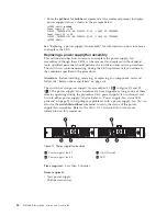
b.
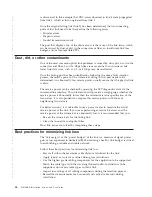
Orient the power supply/fan as shown in Figure 12, with the ac switch on
the left.
c.
Using the handle, gently push the power supply/fan into the chassis until it
is firmly seated.
Attention:
Do not force the installation. If the FRU does not slide in easily,
ensure that it is correctly oriented before continuing.
d.
Tighten the captive screw.
r06b006
Figure 12. Orientation of the power supply and fan assembly
Chapter 3. Operating the SAN06B-R
33
Summary of Contents for SAN06B-R
Page 2: ......
Page 8: ...vi SAN06B R Installation Service and User Guide...
Page 12: ...x SAN06B R Installation Service and User Guide...
Page 14: ...xii SAN06B R Installation Service and User Guide...
Page 24: ...xxii SAN06B R Installation Service and User Guide...
Page 32: ...6 SAN06B R Installation Service and User Guide...
Page 62: ...36 SAN06B R Installation Service and User Guide...
Page 68: ...42 SAN06B R Installation Service and User Guide...
Page 80: ...54 SAN06B R Installation Service and User Guide...
Page 83: ......
Page 84: ...Part Number 98Y5370 Printed in USA GC27 2270 02 1P P N 98Y5370...


