PRESS
HERE
WHEN
INST
ALLING
CARD
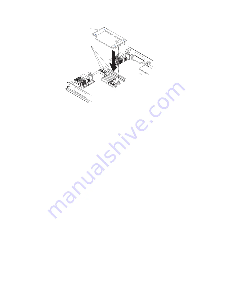
Expansion card
Expansion card
connectors
PRESS
HERE
WHEN
INST
ALLING
CARD
1.
Before you begin, read “Safety” on page v and “Installation guidelines” on
page 15.
2.
Turn off the blade server.
3.
If the blade server is installed in a BladeCenter unit, remove it (see“Removing
the blade server from the BladeCenter unit” on page 16 for instructions).
4.
Open the blade server cover. (see “Opening the blade server cover” on page
17 for instructions).
5.
If an optional expansion unit is installed, remove it (see “Removing an
optional expansion unit” on page 18).
6.
If the system board in the blade server contains an I/O expansion card, such
as a high-speed expansion card, remove the expansion card that is blocking
access to these connectors.
7.
If you have not already done so, touch the static-protective package that
contains the I/O expansion card to any
unpainted
metal surface of the
BladeCenter unit or any
unpainted
metal surface on any other grounded
rack-component for at least 2 seconds.
8.
Remove the I/O expansion card from its static-protective package.
9.
Locate the three I/O expansion-card connectors on the system board in the
blade server. Note that two of these card connectors are identical.
10.
Align the I/O expansion card over the system board in the blade server, so
that the three connectors on the reverse side of the card are correctly aligned
above the three matching expansion card connectors on the system board in
the blade server.
ATTENTION: When you apply pressure to both sides of the expansion card
to seat it in the blade server in step, press the card gently, so that you do
not damage it.
11.
To correctly seat the I/O expansion card in the blade server, press down
firmly on all four corners of the card. The two labels on the top ends of the
card are blue touch points on the I/O expansion card. One of these labels
contains the following statement:
PRESS TO INSTALL
. The I/O expansion
card is automatically secured to the system board through the retention clip
that is located on the reverse side of the card.
Chapter 3. Installing options
27
Summary of Contents for HS12 - BladeCenter - 8028
Page 3: ...BladeCenter HS12 Type 8014 or 8028 Installation and User s Guide...
Page 6: ...iv BladeCenter HS12 Type 8014 or 8028 Installation and User s Guide...
Page 44: ...34 BladeCenter HS12 Type 8014 or 8028 Installation and User s Guide...
Page 54: ...44 BladeCenter HS12 Type 8014 or 8028 Installation and User s Guide...
Page 60: ...50 BladeCenter HS12 Type 8014 or 8028 Installation and User s Guide...
Page 64: ...54 BladeCenter HS12 Type 8014 or 8028 Installation and User s Guide...
Page 72: ...62 BladeCenter HS12 Type 8014 or 8028 Installation and User s Guide...
Page 76: ...66 BladeCenter HS12 Type 8014 or 8028 Installation and User s Guide...
Page 77: ......
Page 78: ...Part Number 60Y1600 Printed in USA 1P P N 60Y1600...


